
VIP member
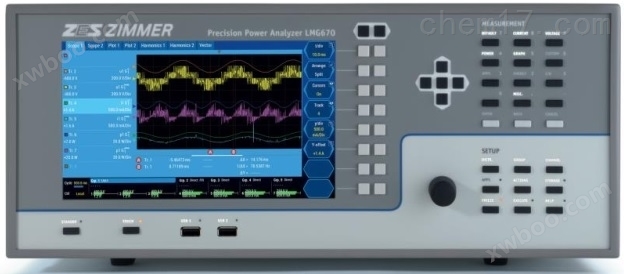
ZES ZIMMER LMG610 German Gaomei GMC-I Power Analyzer
ZES ZIMMER LMG610 German Gaomei GMC-I power analyzer high-frequency bearing current, ballast, high-frequency ferrite core loss, induction heating, ult
Product details
Professional Instrument Equipment and Testing Solution Supplier - JETYOO Industrial&Jianyou (Shanghai) Measuring Instrument Co., Ltd, a former Agilent product technical support engineer-Jian JETKEITHLEY Product Technology Application Engineer-RongyooA trade agency co founded in 2011 with a focus on technical support, aiming to break through the old and establish a new one! Fill the gap of most imported instrument and equipment manufacturers only setting up sales points in China, with weak or no technical support, and agent distributors only specializing in sales, not professional in pre-sales technical Q&A/testing plans, and not professional in after-sales training/maintenance calibration. Our technical sales engineers all have a bachelor's degree or above and over 10 years of experience in the testing industry. With our advanced and unique business philosophy, we specialize in providing instruments and equipment, testing solutions, technical training, and maintenance and measurement services to Chinese users. We are a leading company in the East China region of ShanghaiTechnology orientedA comprehensive service provider for instruments and equipment.
ZES ZIMMER LMG610 German Gaomei GMC-I Power Analyzer
Harmonics: Harmonic and interharmonic measurements are conducted in accordance with IEC/EN61000-4-7 standards, up to a maximum of 2000 times
Process signal: (optional) can input speed and torque sensors of all signal types (analog, frequency signal, RS422, TTL or HTL).
Script Editor: A flexible script editing tool for special applications, facilitating the calculation of all derived variables of power analyzers
Simultaneous measurement of voltage, current, power, and harmonics
Features: List or graphical display
Flexible filter: The frequency, type, and characteristics of the signal filter can be freely set
Plug and play measurement: The current sensor automatically recognizes and supplies power after connection, with easy connection and no risk of configuration errors. Synchronization source: It can synchronize with up to 7 signals of different frequencies simultaneously
Flicker: Measure flicker according to IEC/EN61000-4-15
Sampling values: Obtain high-resolution sampling values and harmonic values directly through the interface
Star delta conversion: In a three-phase three wire system, the line voltage is converted into phase voltage to measure single-phase active power
Touch screen: 8.9 inches, 1024 * 600 resolution, quick access to all important menus
User: DVI/VGA input can be used for external displays or projectors
Interface remote control: real-time display of all device functions, remote operation, and data visualization. Due to the consistency of user image interface, there is no need to reconsider
Storage capacity: Built in high-capacity storage media, even with settingsfastThe cycle can also be used for long-term internal data storage.
Peripheral Communication: Provides outstanding communication capabilities through USB 2.0, G-class Ethernet, RS232, and DVI/VGA
Dual path: Obtaining true effective values and harmonic values of narrowband and wideband simultaneously and without confusion in a single measurement
Sampling rate: High speed sampling rate of up to 1.2MS/s
Data update rate: The minimum update time to obtain true significant values is 30ms
Accuracy: Extremely high measurement accuracy, 0.015% of the measured value+0.01% of the peak range
Dynamic range: The full dynamic range is continuously available, with currents ranging from 500 μ A to 32A, voltages ranging from 3mV to 1000V, and power measurement from standby power to full load (up to 32A) without the need for physical connection changes
Bandwidth: Frequency range from DC to 10MHz
Flexibility: 1-7 power measurement modules can be freely configured and replaced
Continuity: gapless sampling, 18 bit A/D converter, cycle time of 30ms, without interruption when recording measurement values and capturing all relevant events in their entirety
U-I synchronicity: The time offset between voltage and current inputs can be adjusted, with a step size of less than 3ns; low power factor and/or high-frequency measurements
Anti interference: Can work reliably even in severe electromagnetic interference environments
A/B/C module: suitable module for any application, module A: accuracy 0.025%, maximum 10MHz; Module B: Accuracy 0.11%, maximum 500kHz; Module C: Accuracy 0.04%, maximum 10kHz
Ground capacitance: a particularly low ground capacitance of less than 90pF to prevent interference from leakage current
Measurement: A 12-month measurement interval ensures low maintenance costs and instrument availabilitygoodAvailable status
Warranty period: 24 months
ZES ZIMMER LMG610 German Gaomei GMC-I Power AnalyzerEstablish a benchmark for power analysis
For the past thirty years, ZES ZIMMER has only focused on high-precision power measurement technology, so we know that this is not just about
Simple measurement of voltage and current. Anyone attempting to measure power using a general data collection system will quickly need to face its limitations:
How is the common mode rejection situation? Is the test result still reliable when the power factor is 0.01? Is the ground capacitance small enough to resist
Interference from leakage current? In which frequency range does the manufacturer guarantee the measurement accuracy stated? It can be quickly and clearly understood that only specific skills are targeted
Only equipment designed for rate measurement can truly meet these high requirements. ZES ZIMMER's LMG670 stands out in the market because
It has extremely high reliability, precision, and maximum bandwidth - all of which are achieved throughexcellentIdeal conditions for the outcome.
Multiple channel combinations suitable for various applications
The power analyzer provides different accuracy levels, allowing users to choose the appropriate instrument to complete their work. After all, not all applications
NeedtallThe precision. Usually, a normal resolution and accuracy are sufficient. Unfortunately, not all measurement applications are like this.
The following situation often occurs: different measurement points require different bandwidths and accuracy levels under the same measurement configuration. Why is this
LMG670 offers three different input modules that can be installed in the same main chassis to ensure that you can customize the measuring instruments needed for your specific application. This low-priced solution can also meet your requirements well without compromising on accepting low precision
Degree or overuse.
Measurement of three-phase driver motor combination A1 module with high bandwidth and high precision measurement
And internal circuits of the driver, such as high-frequency bearing current, ballast, high-frequency iron
Measure the loss of oxygen core in three-phase driver motor combination, induction heating, ultrasonic waves, etc
Inverter and internal circuit measurement B1 module with high cost-effectiveness and wideband measurement
Single phase input, three-phase output, for example, general laboratory tools, power measurement tools
High precision measurement of C1 module power frequency (50Hz) application in inverter measurement
Single phase input, three-phase output, for example, standby power measurement, energy efficiency, magnetic core loss,
Three phase power measurement, such as motor transformer loss and transformer impedance measurement,
Measurement of power efficiency for household appliances
Analysis of magnetic core loss
Simultaneous measurement of two bandwidths, thanks to dual paths - no compromise, beyond doubt
In traditional power analyzers, the measured signal is first subjected to analog processing, and then converted into a digital signal through an A/D converter for processing, resulting in
The signal can be measured across the entire frequency range, and can also be used as the basis for FFT analysis or further digital filtering through anti aliasing filters.
Due to the limitations of A/D converters, some of their inherent drawbacks will be introduced into traditional devices. If the filter is turned on for measurement
To avoid confusion in FFT analysis, wideband values are discarded. If the filter is turned off, strictly speaking, FFT should not be used. If resistance is not used
The confusion filter performs FFT analysis on the entire frequency range, and the calculated values are suspicious, with a confusion error of up to 50%. For example, it is easy to find that there is none
How can at least 0.5% deviation be ignored. Finally, the validity of the results is also questionable when alternating between filtered and unfiltered measurements
Because this assumes that the signal does not change over time, which is almost non-existent in reality. In addition, this processing procedure is particularly
Other time-consuming activities.
Finally, all proposed measurement methods are merely unsatisfactory compromise solutions. That's why ZES ZIMMER is fundamentally
Design a dual path architecture for signal processing and research and development. Simulation processing is the same as traditional measuring instruments, but subsequent digital processing has been thoroughly implemented
Bottom change. LMG670 is a power converter with two A/D converters in each voltage and current channel in two independent signal paths worldwide
Analyzer. One is used for unfiltered measurement of wideband signals, and the other is used for narrowband signal measurement of anti aliasing filter outputs. Parallel collection
Annotation [T1]: Translation of Text in the Image
Accuracy precision
Bandwidth bandwidth
DualPath Dual Path
A1 channel A1 module
B1 channel B1 module
C1 channel C1 module sample digitization processing allows users to simultaneously obtain two measurement values of the same signal without worrying about the risk of confusion. This unique treatment
Avoiding the drawbacks of all the methods mentioned earlier, ensuring results are obtained in the shortest possible time.
Traditional analyzers
Risk of LMG670 confusion
Quickly obtain results with missing wideband values
FFT analysis of complete wideband numerical dropout
Correct FFT analysis of suspicious and unreliable values
The result is a lengthy measurement
Gapless measurement
In the process of strictly monitoring the energy consumption and efficiency of electrical equipment, in order to fairly compare products from different manufacturers, the new standards
Continuously introducing regulations (such as SPECpower_stsj2008, IEC62301, EN50564). For office computers, servers, or home use
The application of the same principle in electrical appliances: The process of energy consumption always requires long-term analysis, considering all relevant operating conditions. Minimum load (such as
There may be an order of magnitude difference between standby and full load. This makesrefinedMeasurement is very challenging (see "Standby Power Consumption and Energy Efficiency
Measurement "application report. Some measurements require execution for more than a few hours and are seamless. By selecting a sufficiently wide measurement range,
It can avoid changing the range and corresponding data loss. The high basic accuracy of LMG670 ensures that it also achieves near the low limit of the rangerefinedmeasure
result.
Due to minimal delayessencemeasure
Nowadays, frequency converters use fast switching semiconductors to improve efficiency, which produces extremely steep voltage edges, resulting in capacitive currents that cause the shaft to
The insulation of the Chenghe motor is subjected to severe tests, which may lead to premature failure.
Motor filters (such as dU/dt filters) can attenuate steep voltage gradients, although the frequency of the filter itself (usually greater than
The instantaneous oscillation at 100kHz causes its own power loss.
Annotation [T2]: Translation of Text in the Image
Input signal
Frequency domain
Full frequency spectrum
Anti aliasing anti aliasing filtering
Signal signal
Dual Path
The wideband range of LMG670 and the extremely small delay between voltage and current allow for extremerefinedMeasure the power loss of the filter at this frequency
Consumption, including longitudinal measurements at low power factors. It is also suitable for high-frequency measurements at 10MHz, which requires a combination of voltage and current channels
Designed to minimize latency. The delay between the voltage and current channels of LMG670 is less than 3ns, which is equivalent to a phase angle error of less than 1 μ arc at 50Hz
Degree. This makes the instrumentsuitableUsed for measuring power loss at low power factors in transformers, reactors, capacitors, ultrasonic generators, etc.
No additional options or adjustments are required, and the standard configuration of LMG670 is fully capable of handling this measurement task. Usually using voltage and current transmission
Sensor measurement of high-power circuits can improve measurement accuracy by correcting the phase angle of these sensors.
Accurate measurement without limitations
Although LMG670 provides an unparalleled wide range of voltage and current, there are always some applications that require special measurement ranges. Whether you are
We have ready-made solutions for measuring currents of several hundred amperes or voltages of several thousand volts. We offer a wide range of voltage and electricity
The flow sensor can work perfectly with the LMG670 high-precision power analyzer, expanding the measurement range of the instrument to the desired range. we
The plug and play sensor is equipped with a bus system, which allows the LMG670 to automatically recognize and set. This allows for all important parameters,
essenceThe variable ratio factor, delay compensation amount, last calibration time, sensor model, etc. are automatically read by the power analyzer during the measurement process
use. In addition, the sensor is powered by LMG670 and no longer requires a separate external power source.
By using plug and play sensors, users can obtain them without the need for fine-tuninggoodThe result. From the user's perspective, directly measuring and making
There is no difference in measuring with sensors. Of course, sensors from other brands on the market can also be used on the LMG670.
PCT type current sensor
Powerful interface
In addition to GUI (graphical user interface) and connecting to the tested device itself, data exchange with existing computers and software
The most important thing is to determine how well the instrument can complete its predetermined task. Only instruments seamlessly integrated into the entire system
Can be fully utilized by users. The high-speed sampling rate of LMG670 inevitably generates a large amount of data. through the use of
The correct system architecture ensures that measurement data can be transmitted through high-speed interfaces. Even all the important ones
High resolution measurement data of parameters such as voltage, current, active power, etc. can be quickly transmitted within a few minutes
Connected computer. To meet the various needs of different applications, a series of ports are available for use. Apart from a serial port and
In addition to Gigabit Ethernet, there is also a slot for USB 2.0; The instrument can also be equipped with a VGA/DVI output for
Connect an external monitor or projector. In addition, two slots can be modified for future interface standards. through the use of
The integrated synchronization interface enables multiple LMG670s to synchronize with each other. This makes it difficult to operate within the same system
The measurement of multiple LMG670s or the control or connection of LMG670 through an oscilloscope or waveform generator can have the same
A time benchmark. Due to its built-in hard drive, the LMG670 even stores measurement values, settings, and more without connecting to a computer
User defined measurement parameters or graphics for future use. In terms of storage capacity, users have several options available.
The firmware of LMG670 can be quickly and easily upgraded via USB. Process signal interface
It is often necessary to conduct further measurements beyond electrical parameters in order to make a meaningful overall assessment of the performance and efficiency of the tested equipment
Declaration. Therefore, in order to determine the reliable simultaneity between electrical and mechanical events, it is possible to perfectly synchronize these measurement values through LMG670 and
Calculating its true effective value is very important, and a typical application is the analysis of electric drive systems, where torque and speed signals must be combined with electrical parameters
Measure and call. On the contrary, it is also possible that the power analyzer must output measurement results in analog form for further processing, or trigger
The switch operation depends on the measured variable or derived quantity. To meet all these potential demands, LMG670 offers a variety of different options for molding
Input/output interface for analog and digital signals.
Star Triangle Conversion
In a three-phase three wire system, only line voltages V12, V23, V31 and line currents I1, I2, I3 are directly measured. Through star triangle conversion
Option: The three-phase three wire star connection converts the neutral voltage into a phase voltage that is not directly measured, and then the corresponding single-phase active power can be obtained. same
The line current of the three-phase three wire delta connection can be converted into
Phase current. Through these converted values, other factors can be guided
Some variables, such as harmonics. Distortion and non distortion of the power grid or user end
Balance can also be achieved. This enables the use of an external, human
The neutral point created becomes redundant; Although anyone can at any time
To use a neutral point, if all relevant unfavorable conditions are taken into account
If considered (such as increased power loss, etc.).
Easy to use - with or without touch screen
To ensure that LMG670 can be used in any situation, universal availability is particularly important. All display modes and settings are selected
It can be operated through touch screen or buttons, without exception.excellentThe design always connects the buttons to the relevant views and settings options on the screen.
Almost no familiarity is required to effectively use the instrument. The graphical user interface guides users directly to the desired numerical value. The true effectiveness of voltage or current
Two fast, synchronized analog inputs (approximately 150kS/s)
Eight analog inputs
Eight switch inputs (approximately 150kS/s)
Two torque/speed/frequency inputs
Thirty two analog outputs
Eight switch output values, related harmonics, or energy accumulation can usually be obtained by pressing a button. In addition, user-defined views allow for individual measurement values to be displayed separately
Grouping, so all parameters are always clear at a glance. This ergonomic operation method saves time and is effective for LMG670
The use of land has made a direct contribution. On the right side of the display screen, there are eight sets of context related two function keys, whose functions always correspond to the screen
The same line on the upper right is very important for ease of use. Anyone can easily determine the function assigned to the function key at a glance. Dual function key
The design allows for quick configuration of corresponding parameters, eliminating the need for unrelated view switching. When there are questions about functionality and control when operating the instrument,
The relevant chapters of the operation manual can be displayed at any time.
Simultaneous measurement of narrowband and wideband values from the user manual with superimposed help information
The true effective value trend is displayed on the sampling values of 8 signals in two waveform pages
Every click is important
Click on the "Display" function key: Click on the "Phase/CH" function key:
True RMS and harmonic switching display the measured values of all channels or the converted values of the same group. Click "Cycle": cycle time or reference settings
Click on "Grp.": group configuration, synchronization source, filter, etc. Click on horizontal indicator: channel measurement range and sensor configuration
Clear visualization measurement
In order to clarify the functional relationship between physical measurement channels correctly, the power measurement channels (P channels) can be grouped into so-called groups, which are generally
Present as a virtual measurement channel or virtual device outside of the physical channel. The logical combination of P channels depends on the number of connections and phases of the analyzed system.
Due to the flexibility of LMG670, it can even be assembled into unusual and rare configurations, such as phase separated systems and four phase or multi-phase systems, which are both simple and
Reliability, the requirement is that all channels in the same group have the same fundamental frequency and are the same module (A1, B1, C1). this
It will avoid minor errors caused by different technical performance of different module types. One benefit of creating a group is that it changes the settings of the instrument
It should be simple, for example, to make the filter settings that affect all channels within the same group only need to be set once. In addition, derived values such as within the group
The active, apparent, and reactive power of all channels are calculated. When grouping specifies how channels are logically connected, the wiring will specify the measuring equipment
How to connect the input to the measurement circuit, whether it is a star delta circuit or a circuit with a neutral wire. The wiring indicates how the instrument interprets it
Measure the signal. Example: Measurement of frequency converter
Group I uses the two channel three-phase two wire method to measure input power
Rate, CI module is sufficient
Group II uses three channels to measure line voltage and phase current
Flow to obtain output power. Recommend using the A1 module.
Group III uses a single channel group to measure the middle straight
Flow circuit, recommended to use A1 module
Logical combination of channels for different measurement points in the LMG670 setting menu
Electrical drive system
More than half of the electricity produced globally is converted into mechanical motion, making electrical transmission systems increasingly important for transporting goods and people. cross
The loss of the speed controller is as high as 40%, and the current frequency control system can achieve an efficiency level of over 95%. These frequency converters use pulses
Width modulation is used to control the speed of the motor with almost no loss. The purpose is to mutually optimize and adjust the frequency converter and motor to achievegoodOverall efficiency.
Measuring the input power, intermediate circuit, and output power of a frequency converter while measuring the mechanical power of a motor is not simple at all. In addition to sensor technology (using)
Broadband sensors for measuring high currents, high-voltage dividersrefinedThe integration of speed and torque transmitters, as well as the measurement challenges that the instrument must also face
War is a signal on the very steep edge of the output end of the frequency converter. This environment is often described as harsh, not just from the perspective of EMC.
Measure the efficiency of electrical drive systems
1) Inverter input: usually using C1 module is sufficient
Annotation [T3]: Translation of Text in the Image
Frequency Converter
Channel channel
Virtual device, virtual instrument
Annotation [T4]: Translation of Text in the Image
Frequency converter
C Channel C Module
A/B Channel A/B Module
A/B Channel A/B Module
M. Mn torque, speed 2) DC intermediate circuit: According to accuracy requirements, A1 or B1 modules are usually used because DC intermediate circuits have a lot of residual ripple in some cases.
3) Inverter output: According to accuracy requirements, only A1 or B1 modules can be used.
4) Synchronize measurement through process signal interface
Mechanical quantity, 150kS/s
Dual path
Voltage waveform at the output end of the frequency converter
Display. Broadband value ()
Display PWM signal, narrowband value
The display is a sine signal.
Of course, the key issue in analyzing an electrical drive system is: which part of the energy at the output of the frequency converter corresponds to the fundamental frequency related to the motor torque, and which part corresponds to the remaining frequency range, especially the harmonic spectrum? In order to provide aessenceThe answer requires continuous execution of two independent tasks
Measurement: One is the unfiltered wideband power, and the other is the power of the filtered signal at a specific frequency. Then use FFT analysis to measure the harmonic spectrum. This process is very time-consuming, but it cannot guarantee that the initial measurement state will remain unchanged.
The innovative dual path architecture of LMG670 can achieve simultaneous acquisition of all required results in one measurement, which is a precision measure on the markethighThe instrument with the widest frequency range and no confounding effects.
Challenge: LMG670
Synchronous measurement of speed and torque with dual path high precision
High precision measurement of basic oscillations relative to torque A/B/C module anti-interference
Synchronous non confusion measurement harmonic communication interface for losses throughout the maximum frequency range
Range extension star delta conversion plug and play measurement for high current and medium voltage applications
Quickly export data to third-party devices and applications.
switch power supply
Many years ago, the development of power electronics resulted in the huge and heavy transformer power supply being replaced by smaller, lighter, and more efficient switching power supplies
Replaced by. Nowadays, almost all electrical equipment in the power grid can see switch mode power supplies. Although they avoid the drawbacks of previous devices, they also bring
New challenge: Firstly, the conducted emission caused by harmonics is no longer insignificant and must be limited by standards (IEC/EN61000-3-2,
IEC/EN61000-3-2)。 Secondly, high switching frequencies of several hundred kilohertz can lead to electromagnetic compatibility issues, both on the grid side and on the user side
Everyone has it. The role of power measurement technology is to support manufacturers in optimizing their products.
Challenge: LMG670
No gap, high bandwidth continuity for harmonic measurement that meets standards
High frequency analysis with pulse frequency greater than 300kHz, freely adjustable filter with high sampling rate
Fast and gapless sampling of U and I synchronous harmonics for measuring steep switch edges
Reliable measurement of integral and laminated magnetic cores when power factor is less than 0.01
Under the influence of changing magnetic fields, the iron core of the motor experiences losses due to continuous demagnetization and eddy currents, ultimately converting into thermal energy or vibration.
The total loss is related to frequency and should be minimized as much as possible, as they have a significant impact (such as in the battery range of electric vehicles).
The power loss of the magnetic core can be directly calculated from the excitation current of the tested coil and the induced voltage of the induction coil. The magnetic flux density of magnetic core materials can be obtained from
The rectified value of the induced voltage of the induction coil is derived. The magnetic field strength is proportional to the current flowing through the tested coil.
The high-frequency current inside the integral magnetic core can be directly measured, while the large current appearing inside the laminated magnetic core usually requires high-precision sensors for side measurement
Quantity.
Challenge: LMG670
Active poweressenceMeasurement, even when the power factor is less than 0.01, with high bandwidth, high accuracy, and very small voltages. Script editor plug and play measurement
Calculation of multiple derived variables, such as peak magnetic field strength (Hpk), peak U and I synchronous magnetic flux density (Bpk), and relative magnetic permeability (μ a)
Convenient integrated current sensor for measuring high currents
Consistency testing in the aviation and aerospace industry
Especially in the aerospace industry, electromagnetic compatibility between installed systems is extremely important. Therefore, industry directives such as ABD0100.1.8
Limit the range of current harmonics to 150kHz. These harmonics can be analyzed using LMG670. The built-in harmonic analysis function can be used to
Complete, or choose to use external software to obtain detailed sampling values through offline analysis.
Challenge: LMG670
High precision measurement at high frequencies, high bandwidth, and high precision
Analysis of Confused Harmonics up to 150kHz with High Sampling Rate for Harmonics
Powerful FFT analysis up to the 2000th harmonic component
Lighting technology
In order to reduce energy consumption, light bulbs are being replaced with more efficient light sources around the world. Although the necessary operation on the consumer side is only to insert a new product into an existing device, the electrical level difference is actually very large - compared to traditional light bulbs, LED lights, and compact fluorescent lamps
Low energy bulbs are controlled by special electronic ballasts. Some ballasts operate at switching frequencies up to 200kHz, resulting in signal distortion frequencies of up to 1MHz. The first thing manufacturers must do is to prevent damage to the feedback circuit, followed by ensuringgoodThe lifespan of the product. in order to
To achieve the above goals, controlled hot start must be performed frequently, and its proper execution must be verified through appropriate measurements.
Challenge: LMG670
Wide frequency measurement range and high-level measurement accuracy, high bandwidth, and high precision
Proving that the standby power of the ballast can be freely adjusted when the power factor is less than 0.01. The filter has a small capacitance to ground
The minimum ground capacitance is required to avoid synchronous leakage currents U and I during the measurement process
CE compliance testing for harmonics and flicker
If electrical equipment, systems, and devices are to be placed on the EU market, their electromagnetic emission and immunity must meet the levels allowed by EU directives and regulations. Two different types of power grid emissions were tested: harmonics and flicker. Any device with nonlinear loads will generate harmonics. from
Due to the impedance of the power grid, this will cause voltage download and distortion. In addition, certain devices (such as continuous heating equipment, heating furnaces, etc.) control power consumption by suddenly opening and closing, which can cause instability in the grid level due to the impedance of the grid. This generates voltage fluctuations, causing electrical problems
The brightness variation ("flicker") of lighting equipment. By combining a suitable AC power source and reference impedance, LMG670 becomes a tool for harmonic and flicker compliance assessment.
The LMG test suite (attachment) provides an easy-to-use software solution that transforms the execution of electromagnetic compatibility compliance testing into a user-friendly solution
Children's games are so easy. Challenge: LMG670
Verify the stability of the power supply voltage and the absence of harmonics. C module has high precision
Measure signal harmonic flicker at significantly different levels
Clear organization and management of a large number of measurement values, dynamic range testing suite
technical specifications
Measurement accuracy:
A1 module accuracy ± (% of measured value+% of peak range)
Direct voltage input
U*
Voltage sensor input
Enter Usensor
Direct input of current
I * (5mA~5A) current direct input
I*(10A~32A)
Current sensor input
Entering Isensor
Power U */I*
5mA~5A
Power U */I*
10A~32A
power
U*/Isensor
Power Usensor/I*
5mA~5A
Power Usensor/I*
10A~32A
power
Usensor/Isensor
B1 module accuracy ± (% of measured value+% of peak range)
Direct voltage input
U*
Direct input of current
I*(5mA~5A)
Current sensor input
Entering Isensor
Direct input of current
I*(10A~32A)
Power U */I*
5mA~5A
power
U*/Isensor
Power U */I*
10A~32A
C1 module accuracy ± (% of measured value+% of peak range)
Direct voltage input
U*
Direct input of current
I*
Current sensor input Isensor
power
Effective range of accuracy: 1. Sinusoidal voltage and current
2. Environmental temperature (23 ± 3) ℃
3. Preheat for one hour
4. The peak range of power is equal to the peak range of voltage multiplied by the peak range of current.
5. 0 ≤ λ≤ 1 (where λ is the power factor)
6. Voltage and current are between 10% and 110% of the rated range
7. The calibration temperature is 23 ℃
8. Measurement interval of 12 months
All other parameters are calculated based on voltage, current, and power, and their corresponding accuracy and error limits are derived from mathematical relationships.
Note: 1) 1) 2) 3) 4) are only valid in the range of 10~32A.
2. 1) Attachment uncertainty ±
2) Attachment uncertainty ±
3) Attachment uncertainty ±
4) Attachment uncertainty ±
Input specifications:
Voltage input directly into U *:
Rated range (V) 3 6 12.5 25 60 130 250
Maximum true effective value (V) 3.3 6.6 13.8 27.5 66 136 270 440 660 1000
Peak range (V) 6 12 25 50 100 200 3200
Overload protection 1000V+10% continuous, 1500V for one second
Input impedance 4.59M Ω, 3pF
Ground capacitance<90pF
Direct input of current I *:
Rated range (A) 0.005 0.01 0.02 0.04 0.08 0.15 0.3 0.6 1.2 2.5 5 10 20 32
Maximum true effective value (A) 0.0055 0.011 0.022 0.044 0.088 0.165 0.33 0.66 1.32 2.75 5.5 11 22 32
Peak range (A) 0.014 0.028 0.056 0.112 0.224 0.469 0.938 1.875 3.75 7.5 15 30 60 120
Input impedance of about 2.2 Ω, about 600m Ω, about 80m Ω, about 20m Ω, about 10m Ω
Continuous overload protection (A) 10A 32A
Short time overload protection (A) 150A for ten milliseconds
Ground capacitance<90pF
Voltage and current sensor inputs Usensor and Isensor:
Rated range (V) 0.03 0.06 0.012 0.025 0.05 1 2 4
Maximum true effective value (V) 0.033 0.066 0.132 0.275 0.055 1.1 2.2 4.4 Range peak value (V) 0.0977 0.1953 0.3906 0.7813 1.563 3.125 6.25 12.5
Overload protection 100V continuous, 250V for one second
Input impedance 100k Ω, 34pF
Ground capacitance<90pF
Other parameters:
Insulate all voltage and current input channels, other electronic components, and ground
Maximum 1000V CAT III, 600V CAT IV
Synchronous source measurement is achieved by synchronizing the cycle time of the measured signal. The synchronization source can be selected as "power", "external" U (t), or I (t),
It is possible to filter the synchronization source. So reading is very stable, especially with PWM controlled frequency converters and amplitudes
Modulated electronic load
Two sampling value waveform display interfaces with waveform display function, each capable of displaying 8 signals
Trend chart function with two trend chart display interfaces, each capable of displaying 8 parameters for 30ms
Extended graphical interface
(Option L6-OPT-DVI)
VGA/DVI interface is used to connect external displays or projectors
Process signal interface
(Option L6-OPT-PSI)
2 fast analog inputs (150kS/s, 16 bits, BNC connector)
8 analog inputs (100S/s, 16 bits, D-Sub: DE-09 connector)
32 analog outputs (output once per cycle, 14 bits, D-Sub: DA-15 and DB-25 connectors)
8 switch outputs (6 of which have dual connection points, the rest have a common terminal, D-Sub: DB-25 connector)
8 switch inputs (150kS/s, with a common terminal for every group of 4, D-Sub: DB-25 connector)
2 speed/torque/frequency inputs (150kS/s, can connect A, B, Z signals, D-Sub: DA-15 connector)
Star Triangle Conversion
(Option L6-OPT-SDC)
Obtain unmeasured phase voltage (star connection) or phase current (delta connection) in a three-phase three wire system, and calculate the power value of each phase.
Harmonic (Option L6-OPT-HRM)
Harmonic and interharmonic analysis up to 2000 times maximum
Flashing (Option L6-OPT-FLK)
Scintillation analysis according to IEC/EN 61000-4-15 standard
CE Harmonic (Option L6-OPT-CEHRM)
Harmonic analysis according to IEC/EN 61000-3-2/12 standard
LMG Remote extension software, a basic module for computer operation, remote control, and settings
Harmonic flicker testing software (option L6-TEST-CE61K)
Software for testing harmonics and flicker according to IEC/EN 61000 standard
other
size
weight
Protection level
EMC
temperature
Climate category
Input power supply
Desktop 7 modules: 433mm × 177mm × 590, 19 inch cabinet 7 modules: 84HP × 4RU × 590mm
Depending on the installed module: up to approximately 18.5kg
IEC/EN61010, VDE0411, According to EN60529 protection level 1, IP20
EN61326
Operating temperature 0~40 ℃/Storage temperature -20~50 ℃
According to IEC/EN61010 General Environmental Conditions
100~230V, 47~63Hz, Maximum 400W host standard configuration: RS232 interface, USB interface, Ethernet interface, 1 USB flash drive, 1 power cord; Each channel comes standard with two pairs of 1.5m 4mm
Banana head test line with protective cover, one CD.
Current testing accessories:
Type: Closed end transformer, current clamp, flexible
appearance
Model PCTxxx-L6 * 1) L60 Hallxxx * 1) LMG-Z601/2 LMG-Z5xx * 2) L60-Z60/6 L60-Z68 L60 Flex
xxx*1)
Signal type AC+DC AC AC+DC AC
Current range 200A
600A、
2000A
50A、 100A、
200A、 300A、
500A、 1000A、
2000A
100A、
1000A
1500A、
4000A、
10kA
1000A、
3000A
1000Atrms 500A、
1000A、
3000A
Accuracy 0.015% 0.3%~0.9% 0.25% 0.02%/0.05%/0.1%/0.2%
0.5% 2% 2%
Maximum bandwidth DC~1MHz/
DC~100kHz
DC~150kHz 30Hz~1MHz 15Hz~5kHz 30Hz~10kHz/
40Hz~5kHz
DC~2kHz 10Hz~5kHz
Is it powered by the host? * 3) Does it not require power supply
Is it plug and play? Yes
Note: 1) xxx is the current range.
2) Xx: Depending on the current size and accuracy, xx varies. 02 has an accuracy of 0.02% for 1500A, 05 has an accuracy of 0.05% for 1500A, 10 has an accuracy of 0.1% for 1500A, and 20 has an accuracy of 0.0% for 1500A,
42 has an accuracy of 0.02% for 4000A, 45 has an accuracy of 0.05% for 4000A, 50 has an accuracy of 0.1% for 4000A, 62 has an accuracy of 0.02% for 10kA, 70 has an accuracy of 0.1% for 10kA, and 82 has an accuracy of 0.02% for 10kA
(Large aperture type), 90 is 10kA with an accuracy of 0.1% (Large aperture type).
3) The 2000A model requires an external power supply
Diverter LMG SHxxx (- P)*
Resistance (ohms) 001 002 005 010 020 050 100 200 500 * 1) 1000 * 1
Transformation ratio 1.00001 0.50001 0.20001 0.10001 0.05001 0.02001 0.01001 0.00501 0.00201 0.00101
Accuracy 0.15% 0.15% * 2)
Maximum input current
(milliampere)
1000 710 450 320 160 100 70 50 31 22
Note: xxx is the resistance value, - P is 20A one second overcurrent protection type
1) No - P type.
2) The precision of the P-type is 0.3%.
Voltage Test Accessories: Model HST3-x * 1) HST6-x * 1) HST9-x * 1) HST12-x * 1)
Signal type AC+DC
Maximum input voltage 3.15kV 6.3kV 9.45kV 12.6kV
Accuracy of 0.05%
Bandwidth DC~300kHz
Channels 1 to 3
Is it plug and play? No
Note: 1) x is the number of channels.
Secure Connection Attachment:
Model LMG-MAS LMG-MAK1 BOB-CEE3-16 BOB-CEE3-32
Rated voltage 250V 300V 230/400V
Safety level CAT III CAT II
Safety standard IEC/EN61010-1
16A 250V socket for load connection
CEE 7/4
10A 250V
IEC 60320-C14
16A 400V
3L+N+PE,6h
IEC 60309
32A 400V
3L+N+PE,6h
IEC 60309
Other attachments:
Model Function
LMG-IObox25 process signal interface adapter for DB-25 interface
LMG-IObox15 process signal interface adapter for DB-15 interface
LMG-IObox9 process signal interface adapter for DB-9 interface
L60-X-ADSE is used to connect plug and play current accessories to the host
Conversion connector
LMG-Z-AMP artificial neutral point adapter for three-phase three wire star configuration
Maximum connection test (without considering neutral point loss)
Input voltage 500V, maximum ground voltage 600V
LMG-Z-DVx sensor extension cable with shielding, x is the length, 3, 5
10. 15 meters optional
Z941A/B with protective crocodile clip, connected to a 4mm banana plug, with a maximum opening of 39mm and a maximum clamping wire diameter of 30mm.
Rated voltage CAT III 1000V, 32A; A is red, B is black
LMG-Z3xxU voltage test line, rated voltage CAT III 1000V,
1mm2 wire diameter, FF500mA fuse, xx is a number
Words: 08 is 1.5 meters, 09 is 3 meters, 10 is 6 meters,
11 is 10 meters; There are black and yellow colors available
LMG-Z3xxI current test line, rated voltage CAT III 1000V,
32A, 2.5mm2 wire diameter, xx is the number: 08 is 1.5
Meter, 09 is 3 meters, 10 is 6 meters, and 11 is 10 meters;
There are gray and purple colors available
LMG-Z312/3/4 IEEE488 communication cable, 2 is 1 meter, 3 is 2 meters, 4 is 4 meters,
LMG-Z317 RS232 communication cable, 1.8 meters
Online inquiry
-
Contacts
-
Company
-
Telephone
-
Email
-
WeChat
-
Verification Code
-
Message Content
-