
VIP member
YCW series network management optical transceiver
The digital optical transceiver has the following characteristics: ★ All surface mount devices
Product details

The digital optical transceiver has the following characteristics:
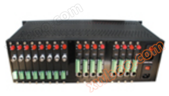
★All surface mount devices. All aluminum alloy 18 inch chassis, independent machine box
★Supports hot swapping. Adopting switch mode power supply
★You can choose FC, ST or SC optical interfaces.
★No electromagnetic interference (EMI), radio frequency interference (RFI), or common ground circuit.
★Adopting non compressed digital video encoding method, 8BIT and 10BIT quantization levels are optional.
★Rich signal interfaces, such as video, data, audio, telephone, network, switch quantity, intercom, etc., can be flexibly configured.
★Using the 1310nm and 1550nm series wavelengths, the typical maximum allowable optical chain loss is 30dB.
★The digital optical transceiver series has two structures: plug-in card and standalone:
The standalone optical transceiver (including 1U chassis and standalone) can be used independently without the need for a separate chassis
Card insertion optical transceiver is used as the center, equipped with an 18 slot chassis.
2、 Product application scope
★Urban Traffic Monitoring System
★Public security and safe city monitoring system
★Highway security and toll collection system
★Building and campus monitoring network
★Industrial monitoring (chemical, steel, petroleum, railway, water conservancy, mining, etc.)
★Military monitoring (warehouses, border defense, guards, national defense, etc.)
★Power oil field and television program transmission system
★Sports venues (live streaming video and audio transmission)
3、 Product Technical Specifications
Video parameters:
Video input/output impedance ----------------------------------------------------------------------
Standard video input/output voltage ------------------------------------1.0Vp-p Type
Video voltage range ----------------------------------------0.6~2.0Vp-p Type
Differential gain (10% -90% APL) ---------------------------------<± 1% type
Differential phase (10% -90% APL) ----------------------------------<± 1 ° type
Signal to noise ratio --------------------------------------->65dB (weighted) (8Bit); >70dB (weighted) (10Bit)
Channel Physical Interface ------------------------------------------------------------------------
Audio parameters:
Audio input/output impedance --------------------------------------600 Ohm (unbalanced)
Maximum input/output voltage for audio: 4.0Vp-p
Frequency response --------------------------------------------------------------------------
Total harmonic distortion ----------------------------------------<0.05%
Signal to Noise Ratio --------------------------------------------------------------------------
Channel Physical Interface -----------------------------------------------------------------------
Data parameters:
Data format --------------------------------------------------------------------------------
Data rate --------------------------------------------------------------------------
Error rate ---------------------------------------10-9
Channel Physical Interface -----------------------------------------------------------------------
Ethernet parameters
Channel Physical Interface -----------------------------------------------------------------------
Data transmission rate -----------------------------------------------------------------------
Working mode ---------------------------------------------------------------------------
Phone parameters
Signal Physical Interface --------------------------------------------------- Standard RJ-11 socket
Voice bandwidth ----------------------------------------8kHz
Working mode: Point to point hotline, program-controlled switch/extension mode
Distortion -----------------------------------------<1%
Signal to Noise Ratio -------------------------------------------->95dB
Switching parameter
Physical interface -------------------------------------------------------------------------
Signal input: Any active or passive alarm, switch input, TTL, RS232/485 or passive switch, button
Signal output --------------------------- Any active or passive alarm, switch output, TTL, RS-232/485 or relay contact output
Channel Physical Interface ---------------------------------------------------------------------
optical parameters
波长----------------------------------------------------- 1310 nm&1470nm~1610nm
Fiber type: 50/125u multimode 62.5/125u multimode 9/125u single-mode
Typical optical output power -------------------------------------------------------------------------
Typical receiver sensitivity -------------------------------------------30 dBm
Optical Interface -----------------------------------------------------------------------------
Conventional Parameters
Working power supply -----------------------------------------------------------------------------
Working temperature: -35 ℃ to 70 ℃
Working humidity: 0-95% without condensation
Size (plug-in card transmission/reception module) -------------------------------------------------------------------
Indicator light description:
Power indicator light: green - the indicator light for normal power connection is on. Not functioning properly and not illuminating.
Light path indicator light: green - abnormal light path, flashing green light. When the light path is normal, it does not light up.
Data indicator light: green - there is data transmission, the indicator light flashes
Video indicator light: green (shared with the light path indicator light) - the green light is on when there is video input or output. There's nothing that doesn't light up.
Ethernet indicator light: Network is normal - the light in the upper left corner of the network port is on. The upper right corner light of the network port is on when the network cable is connected normally. The data transmission is normal, and the light in the upper left corner of the network port is flashing.
4、 Common fault handling
a) Chassis without power supplyCheck if the electrical plug is functioning properly and if the chassis fuse is functioning properly.
b) All video data is abnormalCheck whether the power emitted by the light is normal and whether the received light power is within the acceptance sensitivity.
c) The video image has irregular horizontal stripes or jumpsThe synchronization of video input is incorrect Check whether the ground level of the detection system is equal, especially the ground level of the power supply of the optical transceiver and the ground level between the input and output devices, and whether the video cable connection is good Whether the input signal meets the standard
d) All indicator lights of the optical transceiver are not onCheck if the power adapter is working properly and if the optical transceiver module is fully and correctly inserted into the chassis slot
e) The video indicator light of the optical receiver flashesThe receiver did not receive the correct optical signal; Check if the link loss of the optical fiber is normal The diameter of the optical tail fiber coil is too small (the diameter of the coil fiber must not be less than 20 centimeters) There are impurities on the ceramic interface of the tail fiber (can be gently cleaned with alcohol cotton)
f) The video indicator light of the optical transceiver transmitter is not onThe optical transceiver did not receive the video signal; Check if the video input of the optical transceiver is normal
g) There are snowflakes in the video output of the optical receiver receiverThere are errors during the transmission process; Check if the loss of the fiber optic link is too high, if the diameter of the tail fiber winding is too small (the diameter of the winding fiber must not be less than 20 centimeters), or if the equipment environment temperature is too high, causing unstable transmission.
h) The data of the optical transceiver is abnormalIs the data protocol correct (whether RS232 is used to transmit RS422, etc.); Whether the direction of data transmission is correct (forward, reverse, or bidirectional); Whether the wiring is correct (positive and negative data or transmission and reception, etc.); Is the data input correct
i) Can be combined with device indicator lights to analyze and solve equipment failures.
Note: For long-term safe and stable use of this product, please connect it to outdoor products or install lightning protection facilities when using this product outdoors,And confirm that the product is well grounded.
Online inquiry
-
Contacts
-
Company
-
Telephone
-
Email
-
WeChat
-
Verification Code
-
Message Content
-