
VIP member
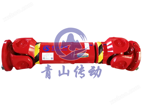
SWCZ type - heavy-duty cross axis universal joint
The heavy-duty SWCZ series is a specially designed universal joint shaft with a special cross design and unique thermal shock application, which impro
Product details
The heavy-duty SWCZ series is a specially designed universal joint shaft with a special cross design and unique thermal shock application, which improves reliability.
Structural Design
Type C - Short flared design without length compensation

D-type - Long shaped design without length compensation

E-type - Scalable Unit Structure Type E - Flanged Shaft Design with Length Compensation

Hirth serration flange bolt hole patterns for end face flange bolt hole arrangement

Table 3: Basic parameters and main dimensions of SWCZ universal joint
Data and Sizes of SWCZ Series Universal Joint Couplings
|
type |
Project item numerical value |
SWCZ |
SWCZ |
SWCZ |
SWCZ |
SWCZ |
SWCZ |
SWCZ |
SWCZ |
SWCZ |
SWCZ |
SWCZ |
SWCZ |
|
Type C |
L |
1540 |
1600 |
1840 |
1920 |
1920 |
2120 |
2280 |
2280 |
2380 |
2480 |
2500 |
2720 |
|
m(kg) |
3150 |
3450 |
4300 |
4680 |
5050 |
6400 |
8420 |
8950 |
10600 |
12100 |
13500 |
16900 |
|
|
D-type |
L |
1940 |
2100 |
2400 |
2500 |
2500 |
2680 |
2950 |
2950 |
3130 |
3200 |
3300 |
3570 |
|
m(kg) |
3220 |
3530 |
4500 |
5400 |
5800 |
7470 |
9980 |
10500 |
12300 |
14500 |
15800 |
19500 |
|
|
E-type |
L |
3230 |
3460 |
3620 |
4000 |
4000 |
4250 |
4580 |
4850 |
4770 |
4950 |
5100 |
5660 |
|
Lv |
250 |
250 |
250 |
250 |
250 |
250 |
300 |
300 |
300 |
300 |
300 |
300 |
|
|
m(kg) |
4880 |
5400 |
8000 |
8450 |
9070 |
11800 |
15900 |
16500 |
19900 |
22000 |
27500 |
34800 |
|
|
Tn(kN.m) |
1640 |
1750 |
2250 |
2500 |
2670 |
3100 |
3800 |
4050 |
5200 |
6500 |
6900 |
9000 |
|
|
Tf(kN.m) |
980 |
1050 |
1350 |
1500 |
1600 |
1860 |
2280 |
2430 |
3120 |
3900 |
4140 |
5400 |
|
|
β(°) |
15 |
15 |
15 |
15 |
15 |
15 |
15 |
15 |
15 |
15 |
15 |
15 |
|
|
D |
680 |
700 |
750 |
780 |
800 |
840 |
900 |
920 |
1000 |
1060 |
1100 |
1200 |
|
|
Df |
680 |
700 |
750 |
780 |
800 |
840 |
900 |
920 |
1000 |
1060 |
1100 |
1200 |
|
|
D1 |
635 |
635 |
695 |
725 |
745 |
775 |
835 |
855 |
915 |
980 |
1015 |
1100 |
|
|
D2(H9) |
550 |
570 |
610 |
640 |
660 |
710 |
740 |
760 |
840 |
840 |
920 |
1000 |
|
|
D3 |
560 |
560 |
620 |
660 |
660 |
660 |
750 |
750 |
790 |
800 |
850 |
900 |
|
|
Lm |
385 |
400 |
480 |
480 |
480 |
530 |
570 |
570 |
595 |
620 |
625 |
680 |
|
|
k |
70 |
70 |
95 |
95 |
95 |
110 |
120 |
120 |
130 |
130 |
130 |
130 |
|
|
n |
24 |
24 |
24 |
24 |
24 |
24 |
24 |
24 |
20 |
20 |
20 |
20 |
|
|
d |
26 |
26 |
31 |
31 |
36 |
38 |
38 |
38 |
50 |
45 |
50 |
58 |
|
|
Flange bolt |
M24 |
M24 |
M30 |
M30 |
M34 |
M36 |
M36 |
M36 |
M48 |
M42 |
M48 |
M56 |
|
Note: 1. The meanings of each code in the table are as follows: 1. Notations
L - Standard length, for scalable models, the length L is in a shortened state L=Standard length, or compressed length for
The minimum length below; designs with length compensation;
Lv - elongation; Lv=Length compensation;
M - Quality; m=Weight;
Tn - nominal torque; Tn=Nominal torque;
Tf - Fatigue torque, which means that under alternating loads, Tf=Fatigue torque, i, e, permissible torque as determined by fatigue strength
Fixed allowable torque; determined according to the fatigue strength
Under updating loads;
β - maximum axis angle; β=Maximum deflection angle;
ML - Mass increased by 100mm; mL=weight per 100mm tube
2. If the measurement unit is not specified in the above table, it shall be measured in millimeters; 2.Millimeters are used as measurement units
Except where noted;
3. Users need to change the standard length, expansion amount, and flange type ruler. 3. Please consult us for customization considerations
Please negotiate with our factory regarding the timing. length,length compensation and flange connections;
Tag Example Example

Online inquiry
-
Contacts
-
Company
-
Telephone
-
Email
-
WeChat
-
Verification Code
-
Message Content
-