
VIP member

Programmable controller (CPU unit) FP-X0 series AFPX0L40MR
New generation multifunctional and economical PLC. The main body is equipped with a hybrid output of relays and transistors.
Product details


The new generation of multifunctional and economical PLC has made its debut
|

 ※1 ※1
|
| ※1 | Low voltage, compliant with EMC directive |
|---|
feature
Performance
Ultra fast computational processing speed
80ns/step (ST instruction): 0-3000 steps ultra high speed
580ns/step (ST command): 3001 steps or more ※
※ (L40, L60 only).
Program memory
L14, L30:2.5k steps
L40, L60:8k steps
Maximum I/O points
A maximum of 3 FP-X0 expansion units can be connected to one control unit.
Therefore, the maximum number of points can reach 180.
In addition, if an extended FP0 adapter is used, a maximum of 236 points can be achieved with the extended FP0 expansion unit.
※ (L40, L60 only)
Network
|
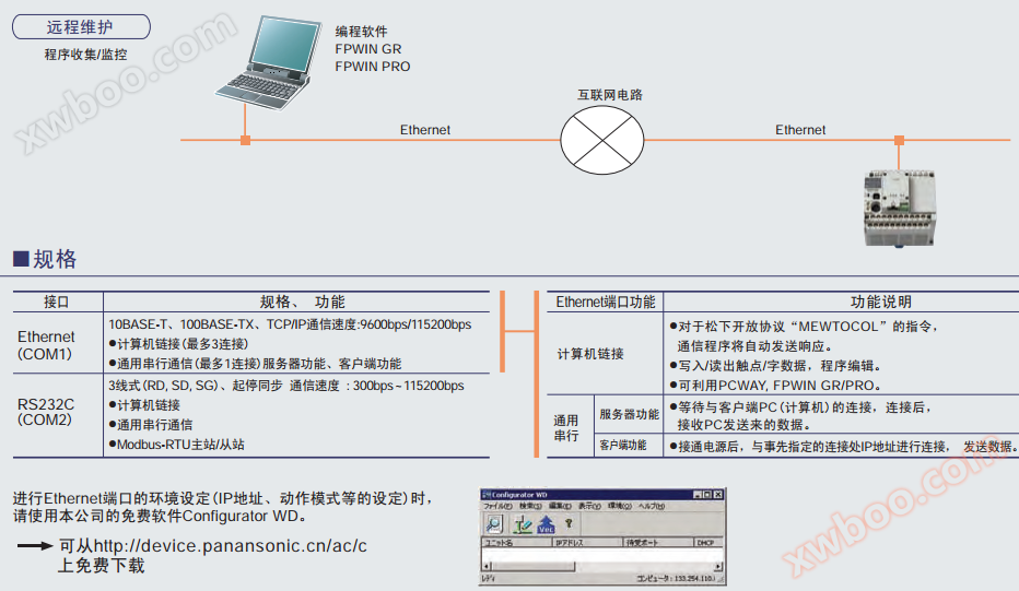
Maximum 2 channels for communication portsThe main body is equipped with an RS232C programming port. In addition, L40MR and L60MR also have built-in RS485 communication ports. Modbus-RTUIt can easily communicate with globally recognized industry standard Modbus RTU (binary) devices without programming. Such as temperature controllers and frequency converters. PLC connectionIf L40MR and L60MR are used, bit/word data sharing can be achieved among up to 16 PLCs. computer connectionIt can easily communicate with Panasonic's open protocol "MEWTOCOL" devices without any program. Such as displays, image processing devices, thermostats, power meters, etc. Universal Serial CommunicationGenerate/send corresponding instructions based on the communication protocol of the other device. In addition, it can also receive mobile data such as measuring instruments, barcode readers, RF-ID, etc.
|
Line Up
Control unit 6 varieties
L14R, L30R, L40R, L60R,L40MR, L60MR
※ All are hybrid outputs of relays and transistors
※ All are AC power supply types
L40MR and L60MR have built-in RS485
Expansion Unit 17 Varieties (FP-X0/FP-X)
FP-X0 expansion unit
E24R, E24T, E24P
E40R, E40T, E40P
E40RD, E40TD, E40PD
E40 is a DC power supply type
FP-X expansion unit
E16R, E16T, E16P
E30R, E30T, E30P
E16X input dedicated unit
E14YR output dedicated unit
The E30 has both AC and DC power supply types
Positioning / Function
Built in 2-axis pulse output function
L14 is a 1-axis, L30/L40/L60 are 2-axis pulse outputs, and are built into the controller body.
The 2-axis built-in type can achieve linear interpolation (limited to L40 and L60 only).
Analog input function
Multi functional analog input (10 bit, 2ch)
Voltage input (0-10v), thermistor input, adjustable potentiometer input.
Basic Performance (Expansion)
■ Adequate maximum I/O points of 180. If the expansion unit of FP0R is further expanded, it can be expanded up to a maximum of 236 points
When it is impossible to predict how many I/O points the customer's own machinery and equipment will need in the future, they may feel hesitant and uneasy when choosing PLC models. However, by using the FP-X expansion unit, the FP-X0 can achieve a maximum of 180 I/O points. Therefore, it can eliminate customers' anxiety and hesitation. And through the use of FP0R expansion units, the number of I/O points can be expanded to 236.
(L14R, L30R have no extension function and cannot be extended)
|

|

|

| Product Name | power supply | Specifications | model |
|---|---|---|---|
| FP-X0 E24R | - | DC input 16 points 2A relay output 8 points |
AFPX0E24R |
| FP-X0 E24T | - | DC input 16 points Transistor (NPN) output with 8 points |
AFPX0E24T |
| FP-X0 E24P | - | DC input 16 points Transistor (PNP) output with 8 points |
AFPX0E24P |
| FP-X0 E40RD | DC | DC input 24 points Relay output 16 points |
AFPX0E40RD |
| FP-X0 E40TD | DC | DC input 24 points Transistor (NPN) output 16 points |
AFPX0E40TD |
| FP-X0 E40PD | DC | DC input 24 points Transistor (PNP) output 16 points |
AFPX0E40PD |
| FP-X E16X | - | DC input 16 points | AFPX-E16X |
| FP-X E14YR | - | 2A relay output 14 points | AFPX-E14YR |
| FP-X E16R | - | DC input 8 points 2A relay output 8 points |
AFPX-E16R |
| FP-X E30R | AC | DC input 16 points 2A relay output 14 points |
AFPX-E30R |
| FP-X E30RD | DC | DC input 16 points 2A relay output 14 points |
AFPX-E30RD |
| FP-X E16T | - | DC input 8 points Transistor (NPN) output with 8 points |
AFPX-E16T |
| FP-X E16P | - | DC input 8 points Transistor (PNP) output with 8 points |
AFPX-E16P |
| FP-X E30T | AC | DC input 16 points Transistor (NPN) output 14 points |
AFPX-E30T |
| FP-X E30TD | DC | DC input 16 points Transistor (NPN) output 14 points |
AFPX-E30TD |
| FP-X E30P | AC | DC input 16 points Transistor (PNP) output 14 points |
AFPX-E30P |
| FP-X E30PD | DC | DC input 16 points Transistor (PNP) output 14 points |
AFPX-E30PD |
If you want to further expand and need more functions, you can use the existing FP0R/FP0 expansion unit to achieve it
After configuring adapters for L40 and L60 control units, up to 3 FP0R/FP0 expansion units can be expanded.
Through [transistor output], [analog input/output], [thermocouple input], [I/O link (network)], corresponding to a wider range of applications.
The control unit is limited to installing only one expansion FP0 adapter. In addition, after the adapter is installed, only 2 FP-X0/FP-X expansion units can be installed.
|

|

|
|
In addition to the included 8cm, additional 30cm and 80cm expansion cables are also available for sale. Can be bent and straightened for use. (Total extension length within 160cm)
special function
■ Pulse output function/high-speed counting function
The FP-X0 has a pulse output function of 1 axis in L14 and 2 axes in L30/L40/L60, which is built into the control unit body. In the past, advanced or positioning specific units were required in PLCs, or two or more multi axis control devices were used. However, for FP-X0, only one unit device is basically used, which can save space and reduce costs.

|
2-axis linear interpolation (L40, L60 only)
Simultaneously controlling two motor axes and causing the robot arm and tool head to move diagonally in a straight line is called 2-axis linear interpolation, which is applied in the picking and placement of palletizers and their components, control of XY workbenches, substrate cutting and processing, and other fields.
|

Built in high-speed counter at 4 o'clock.
|

| model | Input mode | Pulse output (1 axis) | When used for 1ch | When using all ch |
|---|---|---|---|---|
| L14 | single-phase | Pausing | 20kHz | 20kHz |
| Output in progress | 20kHz | 20kHz | ||
| 2 phases | Pausing | 20kHz | 20kHz | |
| Output in progress | 17kHz | 16kHz |
| pattern | Input mode | Pulse output (2-axis) | When used for 1ch | When using all ch |
|---|---|---|---|---|
| L30 | single-phase | Pausing | 20kHz | 20kHz |
| Output in progress | 20kHz | 14kHz | ||
| 2 phases | Pausing | 20kHz | 20kHz | |
| Output in progress | 13kHz | 12kHz | ||
| L40 L60 |
single-phase | Pausing | 50kHz | 33kHz |
| Output in progress | 36kHz | 24kHz | ||
| 2 phases | Pausing | 20kHz | 16kHz | |
| Output in progress | 16kHz | 13kHz |
The body is a hybrid output of relay and transistor. The load capacity of the transistor can reach 0.5
|

The PID command (F356 EZPID) is built-in. The temperature control program only requires one line.
Multi stage temperature control, temperature control linked with timers, variable temperature control based on data calculation results, and multi-point temperature control have expanded the application of temperature control through PLC. By using the new PID command (F356 EZPID), the PID control program has been greatly simplified compared to before. Previously, temperature control through PLC was considered difficult, but now it has become simple and easy to implement. The example on the right is a simple temperature constant control. If combined with touch screen operation and using the F356 instruction, the program only needs one line to describe, and PID control is surprisingly simple.

|
FP-X0 control unit
|


| Product Name | power supply | Specifications | Order Product Number | |||
|---|---|---|---|---|---|---|
| Program capacity | Analog input | RS485 communication | ||||
| FP-X0 L14R | 100~240V AC | 24V DC input with 8 points 0.5A/5-24V DC transistor output 2 points 2A relay outputs 4 points |
2.5k steps | - | - | AFPX0L14R |
| FP-X0 L30R | 100~240V AC | 24V DC input 16 points 0.5A/5-24V DC transistor outputs 4 points 2A relay outputs 10 points |
2.5k steps | - | - | AFPX0L30R |
| FP-X0 L40R | 100~240V AC | 24V DC input 24 points 0.5A/5-24V DC transistor outputs 4 points 2A relay output 12 points |
8k steps | 10bit、2ch | - | AFPX0L40R |
| FP-X0 L40MR | 100~240V AC | 24V DC input 24 points 0.5A/5-24V DC transistor outputs 4 points 2A relay output 12 points |
8k steps | 10bit、2ch | ○ | AFPX0L40MR |
| FP-X0 L60R | 100~240V AC | 24V DC input 32 points 0.5A/5-24V DC transistor outputs 4 points 2A relay output 24 points |
8k steps | 10bit、2ch | - | AFPX0L60R |
| FP-X0 L60MR | 100~240V AC | 24V DC input 32 points 0.5A/5-24V DC transistor outputs 4 points 2A relay output 24 points |
8k steps | 10bit、2ch | ○ | AFPX0L60MR |
| Note) | Expansion unit comes with an 8cm expansion cable |
|---|---|
| Note) | 24V DC input: ± common terminal |
Specifications
Performance Specifications
| project | Specifications | |||||||
|---|---|---|---|---|---|---|---|---|
| L14R | L30R | L40R | L40MR | L60R | L60MR | |||
| control I/O points |
control unit | DC input 8 points Relay output 4 points Tr. Output 2 points |
DC input 16 points Relay output 10 points Tr. Output 4 points |
DC input 24 points Relay output 12 points Tr. Output 4 points |
DC input 32 points Relay output 24 points Tr. Output 4 points |
|||
| FP-X E16 Extended I/O When using the unit |
- | - | Maximum 88 points (Maximum 3 extensions) |
Maximum of 108 points (Maximum 3 extensions) |
||||
| FP-X E30 Extended I/O When using the unit |
- | - | Maximum 130 points (Maximum 3 extensions) |
Maximum 150 points (Maximum 3 extensions) |
||||
| FPOR extension When using the unit |
- | - | Maximum 196 points (Maximum 3 extensions) |
Maximum 216 points (Maximum 3 extensions) |
||||
| Program mode/control mode | Ladder diagram method/cyclic operation method | |||||||
| program memory | FlashROM built-in (do not backup battery) | |||||||
| Program capacity | 2.5k steps | 8k steps | ||||||
| Command language | Basic commands | 114 | ||||||
| Application Commands | 230 | |||||||
| Calculation processing speed | Basic command 0.08 μ s~/step Application command 0.32 μ s (MV command)~ |
3k steps: Basic command 0.08 μ s~/step Application command 0.32 μ s (MV command)~ After 3k steps: Basic command 0.58 μ s~/step Application command 1.62 μ s (MV command) |
||||||
| Basic time | Below 0.15ms | Below 0.18ms | 0.31-0.35ms or less | 0.34-0.39ms or less | ||||
| I/O refresh+base time | When using E24: 0.4ms x number of units When using E40: 0.5ms x number of units When using the extended FP0 adapter: 1.4ms+FP0R/FP0 expansion unit refresh time |
|||||||
| transport calculate use save Storage device |
relay | External input (X) Note 1) |
960 points | 1760 points | ||||
| External output (Y) Note 1) |
960 points | 1760 points | ||||||
| Internal relay (R) | 1008 points | 4096 points | ||||||
| Special internal relay (R) | 224 points | |||||||
| Timer/Counter (T/C) |
256 points note 2) | 1024 points note 2) | ||||||
| Timer (1ms, 10ms, 100ms, 1s units) x 32767 The timer counter within the range can count from 1 to 32767 |
||||||||
| Link relay (L) | none | 2048 points | ||||||
| save store device district domain |
Data Storage (DT) | 2500 words | 8192 words | |||||
| Special Data Storage (DT) | 420 words | |||||||
| Link Data Register (LD) | none | 256 words | ||||||
| File Registration (FL) | none | |||||||
| Index Register (I) | 14 words (IO~ID) | |||||||
| Differential point number | The program capacity is equivalent | |||||||
| master relay (MCR) |
32 points | 256 points | ||||||
| Number of labels (JP+LOOP) | 100 points | 256 points | ||||||
| Step process ordinal number | 128 Project | 1000 Project | ||||||
| Sub program ordinal number | 100 subroutines | 500 subroutine | ||||||
| Number of Interrupted Programs | Input 8 programs, timed 1 program | |||||||
| Sampling tracking | none | have | ||||||
| Save comments | I/O comments, explanations, and block comments can all be saved (No need to backup battery, 328k bytes) |
|||||||
| PLC link function | none | have | ||||||
| Fixed Scan | 0.5ms unit: 0.5ms to 600ms | |||||||
| password | Can be (4 or 8 digits) | |||||||
| Prohibit program upload | can | |||||||
| self-diagnostics | Watchdog timer, program syntax check, etc | |||||||
| Rewrite during RUN process | Can (change capacity in 128 steps simultaneously) However, annotations cannot be rewritten during the process |
Can (change capacity in 512 steps simultaneously) However, annotations can be rewritten during the process |
||||||
| Download in RUN | can | |||||||
| High number counter Note 3) Note 4) |
Ontology input | Single phase 4ch (maximum 20kHz) again 2-phase 2ch (maximum 20kHz) |
Single phase 4ch (maximum 50kHz) again 2-phase 2ch (maximum 20kHz) |
|||||
| Pulse output/ PWM output Note 3) Note 4) |
Ontology output | Pulse output: 1ch (Maximum 20kHz) again PWM output: 1ch (Maximum 1.6kHz) |
Pulse output: 2ch (Maximum 20kHz) again PWM output: 2ch (Maximum 1.6kHz) |
Pulse output: 2ch (maximum 50kHz) again PWM output: 2ch (maximum 3.0kHz) |
||||
| Pulse capture input/ Interrupt input |
8 o'clock (including high count and interrupt input) | |||||||
| timer interrupt | Timed interruption 0.5ms unit: 0.5ms~1.5s, 10ms unit: 10ms~30s | |||||||
| Analog input | none | 2ch (each can be used to input any of the following in each ch) | ||||||
| Potentiometer input Minimum potentiometer resistance value 5k Ω Resolution 10 bits (K0~K1000) Accuracy ± 1.0% F.S.+external resistance accuracy |
||||||||
| Thermistor input Input possible thermistor (Minimum resistance value of external thermistor+external resistance>2k Ω) Resolution 10 bits (K0-K1023) Accuracy ± 1.0% F.S.+external thermistor accuracy |
||||||||
| Voltage input Absolute maximum input voltage 10V Resolution 10 bits (K0-K1023) Accuracy ± 2.5% F.S. (F.S.=10V) |
||||||||
| calendar clock | none | have | ||||||
| Flash ROM backup Note 5) |
According to F12 and P13 command backup |
data memory (2500 words) |
data memory (8192 words) |
|||||
| When the power is disconnected Auto Backup |
Counter 6 o'clock (C250~C255) The counter has a value of 6 points (EV250~EV255) Internal relay 5 points (WR58~WR62) Data storage 300 words (DT2200~DT2499) |
Counter 16 points (C1008~C1023) The counter has a value of 16 points (EV1008~EV1023) Internal relay 8 points (WR248~WR255) Data storage 302 words (DT7890~DT8191) |
||||||
| Backup battery | none | have | ||||||
| RS485 programming port | none | have | none | have | ||||
Note 1) The actual number of points used is determined by the combination of hardware
Note 2) The number of timer points can be increased as needed
Note 3) The rated input voltage is 24V DC at 25 ℃ According to changes in voltage, temperature, and usage conditions, the frequency may decrease
Note 4) The maximum frequency also changes with different usage methods
Note 5) The number of possible writes is within 10000 times The system memory can be set as a save area and a non save area
General specifications
| project | Specifications | |||
|---|---|---|---|---|
| Environmental temperature for use | 0~+55℃ | |||
| Save environmental temperature | -40~+70℃ | |||
| Environmental humidity for use | 10-95% RH (at 25 ℃, there should be no condensation) | |||
| Maintain environmental humidity | 10-95% RH (at 25 ℃, there should be no condensation) | |||
| Withstand Voltage Note 1) Note 2) |
- | control unit | expansion unit | |
| Tr output type | Ry output type | |||
| All input terminals ⇔ All relay output terminals |
2300V AC for 1 minute | - | 2300V AC for 1 minute | |
| All input terminals ⇔ All transistor output terminals |
500V AC for 1 minute | - | ||
| All relay output terminals ⇔ All transistor output terminals |
2300V AC for 1 minute | - | - | |
| Output terminal ⇔ Output terminals (between different common terminals) |
- | 500V AC for 1 minute | 2300V AC for 1 minute | |
| All input terminals ⇔ All power terminals and functional grounding terminals |
2300V AC for 1 minute | 500V AC for 1 minute | ||
| All relay output terminals ⇔ All power terminals and functional grounding terminals |
- | 2300V AC for 1 minute | ||
| All transistor output terminals ⇔ All power terminals and functional grounding terminals |
500V AC for 1 minute | - | ||
| Power terminal ⇔ functional grounding terminal | 1500V AC for 1 minute | 500V AC for 1 minute | ||
| insulation resistance Note 1) |
- | control unit | expansion unit | |
| Tr output type | Ry output type | |||
| All input terminals ⇔ All output terminals | Above 100M Ω (500V DC insulation resistance meter) |
Above 100M Ω | ||
| All relay output terminals ⇔ All transistor output terminals | - | |||
| Output terminal ⇔ Output terminal (between different common terminals) | - | Above 100M Ω | ||
| All input terminals ⇔ All power terminals, functional grounding terminals | Above 100M Ω | |||
| All output terminals ⇔ All power terminals, functional grounding terminals | ||||
| Power terminal ⇔ Ground terminal | ||||
| Vibration | 5-8.4Hz unidirectional amplitude 3.5mm 1 scan/1 minute 8.4-150Hz constant acceleration 9.8m/s2 1 scan/1 minute X. 10 minutes in each direction of Y and Z |
|||
| Impact resistance | 147m/s2X. Four times in each direction of Y and Z | |||
| Noise resistance | 1500V [p-p] pulse width 50ns, 1 μ s (According to noise simulation method) (AC power terminal) |
|||
| Usage environment | No corrosive gases and excessive dust | |||
| EC Directive Usage Specification | EMC Directive: EN61131-2, Low Voltage Directive: EN61131-2 | |||
| II | ||||
| pollution degree | 2 | |||
| weight | ||||
Note 1) The programming port, RS485 communication port, and internal digital circuit section are non insulated.
Note 2) Cut off current: 5mA (initial value at factory)
Note 3) Use a 500V DC insulation resistance meter for measurement.
Power Specifications
AC power supply
| project | Specifications | |
|---|---|---|
| L14R | L30R、L40R、L40MR、L60R、L60MR | |
| rated voltage | 100~240V AC | |
| Voltage range for use | 85~264V AC | |
| inrush current | Below 35A At 240V AC and 25 ℃ |
Below 40A (at 240V AC, 25 ℃) |
| Allow instantaneous power outage time | 10ms (when using 100V AC) | |
| frequency | 50/60Hz(47~63Hz) | |
| leakage current | Below 0.75mA between input and protective grounding terminal | |
| Built in power supply ensures lifespan | 20000 hours (at 55 ℃) | |
| fuse | Built in (non replaceable) | |
| Insulation method | transformer isolation | |
| Terminal screws | ||
Size chart
- Unit: mm
AFPX0L14R
|

AFPX0L30R
|

AFPX0L40R
AFPX0L40MR
|

AFPX0L60R
AFPX0L60MR
|

AFPX0E24R
AFPX0E24T
AFPX0E24P
|

AFPX0E40RD
AFPX0E40TD
AFPX0E40PD
|


option
Wiring tools
| Product Name | Order Product Number | |
|---|---|---|

|
Terminal block screwdriver relayOutput type terminal block (Phonenix system) is required for wiring. |
AFP0806 |

|
Loose wire crimping tool Transistor output type accessoryconnectorRequired during wiring. |
AXY52000 |
assemble parts
| Product Name | Order Product Number | |
|---|---|---|

|
FPO installation plate narrow strip 30 type The mounting plate used for tightening screws. 30mm wide type. |
AFP0811 (including 10) |

|
FPO installation plate narrow strip type The mounting plate used for tightening screws. Narrow strip type. |
AFP0803 (including 10) |

|
mounting plate The mounting plate used for tightening screws. Flat type. |
AFP0804 (including 10) |
input/output cable
| Product Name | Order Product Number | ||
|---|---|---|---|

|
Used for transistor output type I/O cable Attached on one sideconnector10 core loose cable AWG22、0.3mm2、 2 pieces (blue/white) 1 piece |
Length 1m 2 pieces, 1 set |
AFP0521 |
| Length 3m 2 pieces, 1 set |
AFP0523 |
||
| ※1 | For models such as FP0-C10RS, C14RS, E8RS, E16RS, etc., one set (two books) of I/O cables are required. |
| ※2 | For FP0-C16T/E16X and E16T/E16YT models, 1 set (2 pieces) of I/O cables are required each. |
| ※3 | For FP0-C32T/E32T/, 2 sets of I/O cables are required (4 in total). |
Flat cable connector kit (10 cores)

|
Flat cable connector kit core | AFP0808 (4-pack) |
repair parts
| Product Name | Order Product Number | |
|---|---|---|

|
Terminal socket Accessory relayOutput/terminal block type. Repair components. |
AFP0802 (Including 2) |

|
Loose wire crimping socket Belonging to the transistor output type |
AFP0807 (Including 2) |

|
FP0R power cable (1m in length) Attached to FP0R control unit. |
AFPG805 (1 pack) |
Loose wire crimping connector
| Product Name | Order Product Number | Applicable cable size | wire gauge | |
|---|---|---|---|---|
| cable diameter | Remarks | |||
| Loose wire crimping connector | AXW7221FP | AWG#22 | φ1.5~φ1.1 | AWG # 22 12/0.18 |
| AWG#24 | twisted pair | |||
| AXW7231FP | AWG#26 | φ1.3~φ1.1 | twisted pair | |
| AWG#28 | twisted pair | |||
4-point unit relay (power PhotoMOS type)
|

| Contact composition | category | Rated input voltage | 4-point unit relay | |||
|---|---|---|---|---|---|---|
| model | Order Product Number | Quantity per package | ||||
| 1a×4 | DC dedicated (Equipped with AQZ102) |
DC12V | RT3SP1-12V | AY34001 | 1 inner box 20 outer boxes |
|
| DC24V | RT3SP1-24V | AY34002 | ||||
| AC/DC dual-use (Equipped with AQZ204) |
DC12V | RT3SP2-12V | AY35001 | |||
| DC24V | RT3SP2-24V | AY35002 | ||||
| (Note 1) | Dedicated to PhotoMOS power. PA relay cannot be equipped. |
| (Note 2) | Please consult regarding the composition of the contact points. |
4-point unit relay (PA relay type)
|

| Contact composition | Rated input voltage | 4-point unit relay | |||
|---|---|---|---|---|---|
| model | Order Product Number | Quantity per package | |||
| 1a×4 | DC12V | RT3S-12V | AY33001 | 1 inner box 20 outer boxes |
|
| DC24V | RT3S-24V | AY33002 | |||
| (Note 1) | PA relay type. The standard model cannot be equipped with power PhotoMOS. Please make sure to use voltage driven type. |
| (Note 2) | DC5V can also be ordered. Please consult our company. |
| (Note 3) | Please consult regarding the composition of the contact points. |
4-point terminal
|

| category | Rated input voltage | Order Product Number |
|---|---|---|
| PA relay, power PhotoMOS voltage driven type | DC12、24V | AY30000 |
|
|


Relays that can be equipped with 4-point terminals
| Product Name | Order Product Number |
|---|---|
| PA relay | APA3311、APA3312 |
| Power PhotoMOS (voltage driven type) | AQZ10 * D (DC specific type) |
| AQZ20 * D (AC/DC dual-purpose) |
| (Note 1) | Do not equip this product with relays other than those mentioned above, otherwise it may cause abnormal operation, malfunction, and connection equipment failure of the product. |
RT-2 relay terminal
|
|


DIN rail installation type
1. Used for crimping terminals
| Input/output format | Voltage | model | Order Product Number | Quantity per package |
|---|---|---|---|---|
| Input for | DC12V | RT2S-ID16-12V | AY231501 | 1 inner box 10 outer boxes |
| DC24V | RT2S-ID16-24V | AY231502 | ||
| For output purposes | DC12V | RT2S-OD16-12V | AY232501 | |
| DC24V | RT2S-OD16-24V | AY232502 |
2. For direct wiring
| Input/output format | Voltage | model | Order Product Number | Quantity per package |
|---|---|---|---|---|
| Input for | DC12V | RT2S-C-ID16-12V | AY231511 | 1 inner box 10 outer boxes |
| DC24V | RT2S-C-ID16-24V | AY231512 | ||
| For output purposes | DC12V | RT2S-C-OD16-12V | AY232511 | |
| DC24V | RT2S-C-OD16-24V | AY232512 |
Online inquiry
-
Contacts
-
Company
-
Telephone
-
Email
-
WeChat
-
Verification Code
-
Message Content
-