
VIP member

NHR-5500 series manual operator
Overview: The NHR-5500 series manual operator is suitable for use as a backup operator for DCS system circuit regulation control output and intelligen
Product details
| overview | ||||||||||||||||||||||||||||||||||||||||||||||||||||
|
The NHR-5500 series manual operator is suitable for use as a backup operator for DCS system circuit regulation control output and intelligent regulator control output. It can simultaneously input and display given signals and feedback signals, and can be used in conjunction with various sensors and transmitters to measure and display physical quantities such as temperature, pressure, liquid level, capacity, and speed. It can also be used in conjunction with various actuators to control, alarm, and collect data from equipment such as solenoid valves, electric control valves, and frequency converters. |
||||||||||||||||||||||||||||||||||||||||||||||||||||
 instrument panel instrument panel |
||||||||||||||||||||||||||||||||||||||||||||||||||||
|
||||||||||||||||||||||||||||||||||||||||||||||||||||
 Parameter function Parameter function |
||||||||||||||||||||||||||||||||||||||||||||||||||||
|
||||||||||||||||||||||||||||||||||||||||||||||||||||
| Note: The above parameters are all parameters of the instrument. If it is not a fully functional instrument, the parameters corresponding to the unselected function will not be displayed. | ||||||||||||||||||||||||||||||||||||||||||||||||||||
|
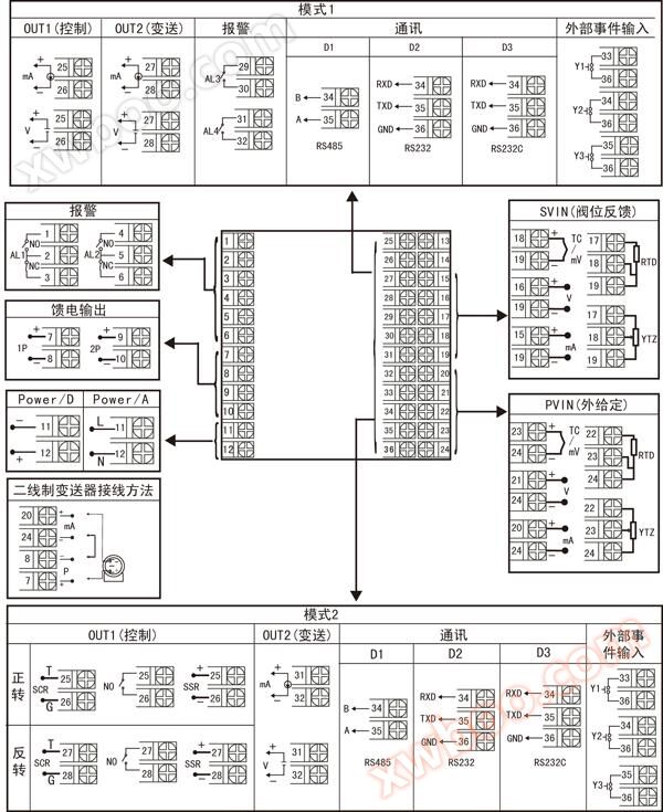
Instrument wiring diagram |
||||||||||||||||||||||||||||||||||||||||||||||||||||
|
||||||||||||||||||||||||||||||||||||||||||||||||||||
|
||||||||||||||||||||||||||||||||||||||||||||||||||||
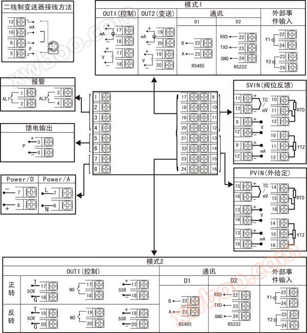 The specification size is F-type wiring diagram |
||||||||||||||||||||||||||||||||||||||||||||||||||||
| Note: In the above wiring diagram, if different functions are marked on the same group of terminals, only one function can be selected. If RS485 and RS232 are connected to the same set of terminals, only one can be selected. | ||||||||||||||||||||||||||||||||||||||||||||||||||||
|
instrument selection |
||||||||||||||||||||||||||||||||||||||||||||||||||||
|
NHR-5500□-□/□-□/□/□/□/□( )-□-( ) ① ② ③ ④ ⑤ ⑥ ⑦ ⑧ ⑨ ⑩ |
||||||||||||||||||||||||||||||||||||||||||||||||||||
|
||||||||||||||||||||||||||||||||||||||||||||||||||||
| remarks: | ||||||||||||||||||||||||||||||||||||||||||||||||||||
| 1. When selecting, please refer to the wiring diagram to choose the function. Due to the small size of instrument wiring terminals, they may not have full functionality, and some functions can only be selected from one of them on the same group of terminals. 2. The F-type instrument does not come with an RS232C printing interface. 3. For instruments with specifications D and E, if there is an alarm function between the wiring terminals 25-36, the relay contact capacity is AC125V/0.5A and DC24V/0.5A. For instruments with other specifications, the relay contact capacity is AC220V/2A and DC24V/2A. 4. When the instrument selects the switch control output function (forward and reverse output), the alarm output selects 2-limit alarm. 5. When writing the model, it must be complete, and any function items that have not been selected cannot be omitted and must be supplemented with an "X". Example 1: NHR-5500A-27/27-0/2/X/X-A (analog control). Example 2: NHR-5500A-14/27-K1/0/2/D1/X-A (valve position forward and reverse control). |
||||||||||||||||||||||||||||||||||||||||||||||||||||


Online inquiry
-
Contacts
-
Company
-
Telephone
-
Email
-
WeChat
-
Verification Code
-
Message Content
-