
VIP member

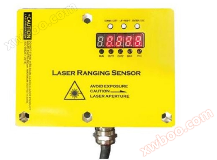
High frequency laser ranging sensor DOB-TLS/L1
High frequency laser ranging sensor DOB-TLS/L1
Product details
I. Overview
Basic Function Introduction
The range can be set, up to a maximum of 40 meters
3cm absolute accuracy (5cm absolute accuracy under weak reflectivity, 7cm absolute accuracy under extreme weak reflectivity)
Real time display of measurement results on digital tube
LED status display
4-20mA analog output
100Hz measurement frequency
2-channel relay output (supports NPN/PNP), can independently set threshold
Measurement distance correction
Basic parameter setting
Multiple modes support multiple application scenarios
RS485 interface, supporting Modbus RTU protocol (optional)
Electronic parameters
1)Limit value, when reverse polarity protection operates in a circuit with short-circuit protection: maximum8 A.
2)ForTLS-xxxx:UV > 15 V.
3)Not lower or higher thanUVtolerance.
4)No load.
performance
|
measurement range |
0-5M ,0-10M,0-15M ,0-20M,0-30M |
|
Measuring objects |
Natural objects |
|
resolution |
1mm |
|
precision |
precision1.5 mm+d 0.5‰ |
√ Range can be set, maximum30rice
Real time display of measurement results on digital tube
√LEDstatus display
√ Voltage analog output
√ Over limit relay output (supports)NPN/PNP)
√ Measurement distance correction
√ Basic parameter settings
√RS485Interface, supportsModbu s RTUagreement.
|
frequency |
5Hz,10Hz, 20Hz, 30Hz |
|
Output time |
≥4 ms6) |
|
light source |
Red laser |
|
Laser grade |
1 (IEC 60825-1:2014, EN 60825-1:2014)7) |
|
Typical photoelectric size distance () |
15 mm x 15 mm (10 m) |
|
Other functions |
Adjustable sliding average: fast/slow,Switching mode: Distance object(dto),Digital output that can be taught, parameterized, and reversed,Adjustable hysteresis phenomenon,Teaching style, parameter adjustable, reversible analog output terminal,Multi functional input: laser off/外部示教/disable,Turn off the display screen,Restore factory settings,Lock the user interface |
|
Average laser service life(25At ℃) |
100,000 h |
1)correspond to1 σ.
2) 6% . .. 90%reflectance.
3)Depending on the method of forming the average value set: fast/slow.
4) 90%reflectance.
5)Introduce the object into the measurement range from the side.
6)Continuously changing the distance to the object within the measurement range.
7)wavelength658 nmMaximum power:120 mWPulse duration:2.5 nsContact rate:1/400.
|
digital output |
|
|
|
|
quantity |
1 1) 2) 3) |
|
|
type |
PNP,NPNoptional |
|
|
Maximum output currentIA |
≤100 mA |
|
Analog output terminal |
|
|
|
|
quantity |
1 |
|
|
type |
voltage/Current output optional |
|
|
voltage/current |
0V-10V/4mA-20mA,≤300Ω |
|
|
resolution |
12bit |
|
Multi functional input(MF) |
|
1 x3) 4) |
|
lag |
|
10mm. ..1000mm |
interface
environmental parameters
|
Operating environment temperature |
–15 °C . .. +50°C |
|
Storage environment temperature |
–20 °C . .. +60°C |
|
Maximum relative air humidity (non condensing) |
≤85 % |
|
Type: Ability to resist environmental light |
40,000 lx |
|
Vibration resistance |
EN 60068-2-6, EN 60068-2-64 |
|
Impact resistance capability |
EN 60068-2-27 |
Instructions for Use
The user interaction interface of this product mainly consists of digital tubesLEDComposed of indicator lights and buttons. Digital tube andLED
Indicator lights are used for displaying product information, and buttons are used to modify product parameters
LED
This product has5 LED lights are used to display the basic status of the product. For detailed instructions, please refer to the table below.
|
name |
effect |
description |
|
RUN |
Indicate the operating status of the laser sensor |
LED flashing indicates that the laser sensor is in operation |
|
OUT |
Indicate the output status of the over limit relay |
When an over limit event occurs, the relay drives the outputThe LED light is on; When there are no exceeding events, the light will turn off |
|
MAX |
Indicate whether the measurement result exceeds the range |
When the measurement result exceeds the range,MAX light on |
|
MIN |
Is the measurement result less than0 |
When the measurement result is negative,MIN light on |
|
PRO |
1. Indicates that it is currently in setup mode 2. Indicate product abnormality |
1. The user enters the configuration interface,The PRO light is constantly on, and when the configuration is completed, the PRO light will turn off when entering the main interface; 2. If there are any abnormalities in the productPRO light flashing |
button
This product has a total ofThree physical buttons are used to create six virtual buttons through short and long presses, namely up, down, left, right, confirm, and return.
|
physical button |
short press |
long press |
position |
|
button1(ENTER/ESC) |
confirm |
return |
the leftmost |
|
button2(UP/LEFT) |
up |
left |
middle |
|
button3(DOWN/RIGHT) |
down |
right |
On the far right |
Note:
1. After pressing and releasing the button, the corresponding event will be triggered
2. Short press refers to pressing the finger down0.2~0.5 seconds and then release; Long press refers to pressing for more than 0.5 seconds and then releasing
seven-segment display
This product hasFive 8-segment digital tubes are used as display interfaces, which can display numbers and English letters. When combined with buttons, they can complete the functions of product information display and parameter setting. Please refer to Appendix A for the display effect of the digital tube.
image1 shows the basic interface operation process of the product.
After the product is powered on, it defaults to the main interface and displays the current measurement results in real-time. When pressedWhen ENTER, enter the menu selection interface; On the menu selection interface, use the up and down buttons to switch between submenus, and press ENTER to enter the corresponding submenu interface. Press the ESC button on the menu selection interface to return to the main interface.
In the submenu interface, use the up, down, left, right buttons to modify the parameters, and then pressENTER or ESC returns to the menu selection interface (if ENTER is pressed to save changes, if ESC is pressed to undo changes).

Main Interface
LordThe interface is the measurement result display interface, which displays the current measurement result in meters after the decimal pointThree people.
By default, the main interface will be displayed when powered on. Press the buttonENTER switches to the menu selection interface. Press ESC on the menu selection interface to switch back to the main interface.
Zero position correction
Select through the up and down keys on the menu selection interfaceCALIB, Press ENTER to enter the zero position correction interface. At this point, the interface displays the calibrated data, which is updated in real-time by adjusting the calibration values.
Fix this product onto the test rail through the positioning hole and place it at a certain distance from the positioning hole (e.gPlace obstacles within 1 meter. Modify the calibration value by pressing the up, down, left, and right buttons to make the displayed data on the interface match the actual distance (such as 1 meter). Up and down keys increase or decrease the calibration value; Use the left and right keys to modify the amplitude of the calibration value increase or decrease, and the modified number will be indicated by flashing.
After the calibration is completed, pressENTER will display the current data used for calibration. At this point, you can also use the up, down, left, and right buttons to adjust the calibration data, using the same method as above. Press ENTER again to complete zero position correction; If ESC is pressed, the modification will be undone and the menu selection interface will be returned.
Sampling mode setting
To cope with different application scenarios, this product supports the following4 sampling modes.
Slow mode is used for precise measurement of distance to stationary objects, characterized by high accuracy and slow response speed; Fast mode is used to measure fast-moving objects, characterized by fast response speed and reduced measurement accuracy.
|
Sampling mode |
Data sampling frequency |
Calculate the amount of data used |
|
Slow speed(1.SLOW) |
5Hz |
8 |
|
Normal(2.NORM) |
10Hz |
8 |
|
fast1(3.FST1) |
20Hz |
4 |
|
fast2(4.FST2) |
30Hz |
2 |
Sampling mode description
Working mode setting
This product supports relay over limit alarm output. Set the normal working range of the product by setting the working mode; When the measurement result exceeds the normal range, the driving relay will activate.
|
working mode |
Lower limit of normal range |
Upper limit of normal range |
|
pattern1(1.mod1) |
0 |
limit3(Limit3) |
|
pattern2(2.mod2) |
limit2(Limit2) |
limit3(Limit3) |
|
pattern3(3.mod3) |
(limit1+limit2)/2 |
(limit2+limit3)/2 |
Working mode description

Select the working mode setting interface on the menu selection interface, use the up and down keys to select the desired working mode, and pressEnter to confirm the modification. If you want to undo the modification, press ESC to directly return to the menu selection interface.
Note: Limit1, limit2, and limit3 must be set in ascending order, with limit3 being the largest and limit1 being the smallest
If limit1, limit2, and limit3 are not set in ascending order, they will be reordered when calculating the range
Limit setting
fromSelect the menu selection interface to enter the limit setting interfaceThree limit parameters can be set, which are determined by the working mode.
The setting of limit parameters is divided into two stages: initial value selection stage and fine-tuning stage.
Initial value selection stage
The initial value of the limit parameter can be obtained from three sources: system configuration, current measurement results, and zero
Enter the limit setting interface from the menu selection interface, which displays the current measurement results. Press directly at this timeENTER, Select system configuration as the initial value for fine-tuning and enter the fine-tuning phase; Press the up button (or left button) to use the current measurement result as the initial value for fine-tuning and enter the fine-tuning phase; Press the down key (or right-click) to set zero as the initial value for fine-tuning and enter the fine-tuning phase.
Fine-tuning phase
In the limit adjustment stage, adjust the size of the limit by pressing the up and down keys, and change the amplitude of the adjustment by pressing the left and right keys.
After the fine-tuning is completed, pressENTER saves the modifications and returns to the menu selection interface. Press ESC to undo modifications and return to the menu selection interface. If the limit value still needs to be set at this time, press ENTER in the menu selection to enter the initial value selection stage again and complete the subsequent operations.
range setting
This product can be set to different ranges according to requirements. The currently supported ranges are 1m, 3m, 5m, 10m, 15m, 20m, and 30m. Analog output corresponds to 10V output at full scale, and 0m corresponds to 0V output.
Select the range setting interface from the menu selection interface and use the up and down keys to choose different ranges. pressENTER saves the modifications and returns to the menu selection interface; Press ESC to undo the modifications and return to the menu selection interface.
Restore factory settings
On the menu selection interface, select to enter the factory reset interface, and use the up and down keys toSwitch between YES and NO. When YES is selected, pressing ENTER will restore the factory default configuration and return to the menu selection interface; Pressing ENTER or ESC when selecting NO will directly return to the menu selection interface.
Quick Start
By following these steps, you can quickly purchase this product.
1. range setting
2. Zero calibration
3. Set sampling mode
4. Set working mode and limit values
5. Install and test voltage analog output and relay drive output
Application of laser ranging sensor products:
Measure the length, width, thickness, and position of various plates, such as steel plates, middle plates, rubber plates, plastic plates, etc
Measure the accurate location of bulk solids, liquids, anti-corrosion materials, and radiation objects in various containers and large tanks
Measure the position of objects, especially those moving on tracks, such as cranes and track conveyors, during various movements
Bridge static deflection online (wireless) monitoring system
Tunnel overall deformation online (wireless) monitoring system, tunnel key point deformation online (wireless) monitoring system
● Balance monitoring system
● Thickness dimension monitoring system
Mine elevator, large hydraulic piston height monitoring, positioning monitoring system
Online inquiry
-
Contacts
-
Company
-
Telephone
-
Email
-
WeChat
-
Verification Code
-
Message Content
-