|
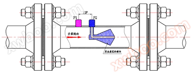 |
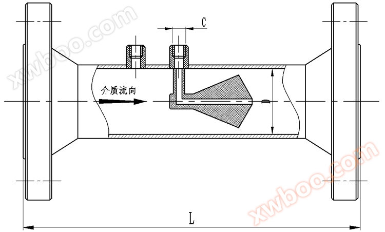
The V-cone flowmeter, like other differential pressure instruments, is also based on the principle of flow continuity and Bernoulli equation to calculate the flow rate of fluid conditions. We know that in the same closed pipeline, when the pressure decreases, the velocity will increase. When the medium approaches the cone, its pressure is P1. When the medium passes through the throttling area of the cone, the velocity will increase and the pressure will decrease to P2. As shown in the figure, both P1 and P2 are led to the differential pressure transmitter through the pressure port. When the flow rate changes, the differential pressure value will increase or decrease accordingly. That is to say, for stable fluids, the magnitude of the flow rate is directly proportional to the square root of the differential pressure. When the flow rate is the same, the larger the cone throttling area, the greater the differential pressure value generated.
|
|
 |
 |
1. Catheter;
2. Connect the flange;
3. V-cone core body;
4. High pressure tapping tube;
5. Low pressure tapping tube;
6. Support pipe+low-pressure outlet pipe
|
|
 |
|
The permanent pressure loss is low, and only one-third of the orifice plate is familiar with the Venturi tube.
The range is much wider than that of other differential pressure types, with a normal range of 10:1.
The accuracy of the V-cone flowmeter with high measurement precision is ± 0.5%.
The repeatability of the V-cone flowmeter with good repeatability is ± 0.1%.
The requirements for straight pipe sections are low, only requiring extremely short straight pipe sections (front 1-3D, back 0-1D).
The structure design of the self rectifying, self-cleaning, and self-protection flowmeter is a fluid sweep type structure, with no dead corners of scale accumulation. The boundary layer effect formed by the unique structure prevents wear on key parts of the throttle component.
Anti vibration, high temperature, and high pressure flow sensors are pure mechanical bodies without moving parts, so they are resistant to high temperature, high pressure, corrosion, and vibration.
The integrated structure design of the V-cone flowmeter integrates the throttling element, sensor, intelligent circuit, display, and communication unit. During installation, users only need to weld the matching flange, which eliminates the pressure pipeline of traditional differential pressure flowmeters, simplifies installation, reduces installation time and cost, and is convenient for users to use.
|
 |
|
 |
|
Nominal diameter: DN25-DN1600 (diameters larger than DN1600 can also be used)
Tested media: liquid, gas (including natural gas), steam
Basic error: ± 0.5%, ± 1.5%, ± 2.5%
Work pressure: ≤ 26.0 MPa
Temperature of the tested medium: < 550 ℃
Requirements for straight pipe section: upstream 0-3D, downstream 0-1D
Power supply: 24V DC (requires differential pressure transmitter)
Display: 8-bit LCD displays instantaneous flow and cumulative flow (equipped with a flow integrator)
Output signal: (1) 4-20mA DC flow signal (2) HART protocol compliant output signal
Explosion proof performance: intrinsic safety type IbIICT5
Protection performance: IP65
|
 |
|
Flange execution standards: JB/T81-1994, JB/T82.1-1994, JB/T82.2-1994
|
|
| Nominal Diameter |
D L (mm) |
C |
Nominal Diameter |
D L (mm) |
C |
| DN25 |
150 |
M12*1.5 |
DN350 |
900 |
M20*1.5 |
| DN32 |
165 |
M12*1.5 |
DN400 |
1050 |
M20*1.5 |
| DN40 |
200 |
M12*1.5 |
DN450 |
1150 |
M20*1.5 |
| DN50 |
250 |
M20*1.5 |
DN500 |
1260 |
M20*1.5 |
| DN65 |
275 |
M20*1.5 |
DN600 |
1380 |
M20*1.5 |
| DN80 |
300 |
M20*1.5 |
DN700 |
1500 |
M20*1.5 |
| DN100 |
350 |
M20*1.5 |
DN800 |
1600 |
M20*1.5 |
| DN125 |
400 |
M20*1.5 |
DN900 |
1750 |
M20*1.5 |
| DN150 |
450 |
M20*1.5 |
DN1000 |
1850 |
M20*1.5 |
| DN200 |
550 |
M20*1.5 |
DN1400 |
2000 |
M20*1.5 |
| DN250 |
650 |
M20*1.5 |
DN1600 |
2200 |
M20*1.5 |
| DN300 |
700 |
M20*1.5 |
DN1500 |
2500 |
M20*1.5 |
|
 |
| model |
Remarks |
| HLVZ |
V-Cone flowmeter |
| |
code |
Classified by structure |
| |
01 |
Pipeline type |
| |
02 |
embedded |
| |
03 |
plug-in |
| |
code |
Caliber (mm) |
| |
25-3000 |
DN25-DN300 |
| |
code |
Pressure rating (MPa) |
| |
1.6 |
1.6 |
| |
2.5 |
2.5 |
| |
4.0 |
4.0 |
| |
6.3 |
6.3 |
| |
10 |
10 |
| |
16 |
16 |
| |
26 |
26 |
| |
code |
medium |
| |
1 |
liquid |
| |
2 |
gas |
| |
3 |
steam |
| |
code |
Compensation form |
| |
N |
Without pressure or temperature compensation |
| |
P |
With pressure compensation output |
| |
T |
Equipped with temperature compensation output |
| |
code |
Differential pressure range of transmitter |
| |
0 |
Micro differential pressure range |
| |
1 |
Low differential pressure range |
| |
2 |
Medium differential pressure range |
| |
3 |
High differential pressure range |
| |
code |
Is there an on-site display |
| |
W |
Throttle device sensor |
| |
X |
Intelligent throttling device (flowmeter) |
|
|

|
|
1. Media name
2. Inner and outer diameter of pipeline (mm)
3. Choose the form of V-cone flow sensor
4. Flow units (kg/h, t/h, m3/h, Nm3/h)
5. Common flow rate, minimum flow rate, maximum flow rate, and calibrated flow rate
6. When the medium is in a gas standard state, the 0 ℃ standard condition or 20 ℃ standard condition should be specified.
7. Working pressure (MPa): a. Absolute pressure b. Gauge pressure
8. Fluid temperature (℃): highest, lowest, and commonly used temperatures
9. Fluid density (kg/m3 or kg/Nm3)
10. Fluid viscosity (mPa. s)
11. Relative temperature
12. Gas composition volume percentage (for mixtures of two or more gases)
13. Pipeline device a, horizontal b, from bottom to top
14. Pipeline flange a. According to the flange standard specification, the code is provided for the flange standard and model b. Party B provides drawings
be careful:
To measure water and water vapor, (1), (2), (4), (5), (7), (8), (13), and (14) must be provided
Measurement of general gases requires the provision of (1) to (14)
To measure general solutions and oils, (1), (2), (4), (5), (7), (8), (9), (10), (13), and (14) must be provided
Each data item must be filled with a specific numerical value for the process design, please do not fill in a range of approximately how many
|
|

|
|
(1) Measure liquid flow rate
(a) It is best to install the differential pressure transmitter below the inner cone device (Figure 1.1) to prevent gas in the liquid from entering the pressure pipe and transmitter.
(b) If the transmitter has to be installed above the inner cone device (Figure 1.2), in order to reduce the entry of gas in the liquid into the pressure pipe, a U-shaped bend should be installed between the inner cone device and the pressure pipe, and the lower end of the bend should be at least 1 meter below the center of the pipeline.
(c) On horizontal or inclined pipelines, if the pressure pipe is installed in the upper half of the inner cone device, gas will accumulate inside the pressure pipe. If it is installed in the lower half of the inner cone device, sediment will fall into the pressure pipe. Therefore, the pressure conduit should be led out from both ends of the horizontal centerline of the inner cone device, or from a horizontal downward angle of less than 45 degrees.
|
|
|
|
|
(2) Measure steam flow rate
(a) In order to ensure that the transmitter is not affected by high steam temperature, two condensers located at the same height must be installed between the transmitter and the inner cone device, and the condenser, pressure pipe, and high and low pressure chambers must be filled with condensed water to avoid the impact of high temperature on the transmitter.
(b) It is best to install the differential pressure transmitter below the inner cone device (Figure 2.1) to prevent gas from entering the pressure pipe and transmitter. The condenser should be installed as close as possible to the inner cone device.
(c) If the differential pressure transmitter has to be installed above the inner cone device (Figure 2.2), the condenser should be installed above the differential pressure transmitter.
(d) Both installation methods mentioned above are equipped with valves near the transmitter for flushing the pressure pipe. At the same time, insulation layer should be added to the pressure pipe between the inner cone device and the secondary condenser.
|
|
|
|
 |
|
The V-cone flowmeter can work normally even under harsh conditions, but for long-term safe and stable use, please pay attention to the following points during installation:
(1) The installation site shock and vibration V-cone flowmeter is designed to withstand a certain degree of shock and vibration when it leaves the factory. But it should also be installed as much as possible in places with no or minimal vibration.
(2) Please try to avoid installing the flowmeter in places with large temperature changes. If the installation location is directly exposed to thermal radiation or sunlight, waterproof, thermal insulation, radiation and ventilation measures should be taken.
(3) The installation site environment air conditions for V-cone flow meters should be avoided as much as possible in corrosive environments. If used in corrosive environments, good ventilation should be provided and attention should be paid to avoiding corrosive gases or liquids from entering the instrument.
|
 |
| Fault phenomenon |
cause |
Solution |
| No differential pressure signal output |
The high and low pressure valves are not open |
Open the high and low pressure valves |
| The balance valve is not tightened |
Tighten the balance valve |
| Differential pressure signal output too small |
Differential pressure range mismatch |
Adjust the transmitter range |
| Leakage of high-pressure impulse pipe |
Find and eliminate leaks |
| Differential pressure signal output too large |
Low pressure impulse pipe blockage |
Clean the pressure pipe |
| Differential pressure range mismatch |
Adjust the transmitter range |
|
|
 |
|
Comes with attachments
Pressure pipe, connecting flange, conduit
Optional Accessories
Condenser, socket weld gate valve, three valve group, needle globe valve
Optional related products
Pressure transmitter, temperature transmitter, flow meter integrator, intelligent differential pressure transmitter.
|
 |
 |
 |
 |
|
|
 |
 |
 |
| |
|