
VIP member

GDL vertical clear water pipeline multi-stage pump
The GDL vertical clear water pipeline multi-stage pump system is designed and manufactured based on advanced foreign products. The impeller, guide van
Product details
Model Meaning

Product Introduction
The GDL vertical clear water pipeline multi-stage pump system is designed and manufactured with reference to foreign products. The impeller, guide vanes, and guide housing are formed by stamping, stretching, and welding stainless steel plates, and use hard alloy mechanical seals and guide bearings. It has significant characteristics such as small size, light weight, high efficiency, energy saving, low vibration and noise, smooth operation, long service life, vertical installation, small footprint, light weight, and beautiful appearance, making it an ideal replacement product.
Product Features
1. The GDL vertical clear water pipeline multi-stage pump is a vertical structure with the characteristics of small footprint. The pump center of gravity coincides with the pump foot center, resulting in smooth operation, low vibration, and long service life.
2. The GDL vertical clear water pipeline multi-stage pump has the same diameter and is on the same horizontal centerline, without changing the pipeline structure, and can be directly installed at any part of the pipeline, making installation extremely convenient
3. The motor with a rain cover can be directly placed outdoors for use without the need to build a pump room, greatly saving infrastructure investment.
4. The head of the GDL vertical clear water pipeline multi-stage pump can be adjusted by changing the number of pump stages (impeller count) to meet different requirements, so it has a wide range of applications.
5. The shaft seal adopts a hard alloy mechanical seal, which is reliable, leak free, and has minimal mechanical losses.
6. Efficient and energy-saving, with a beautiful appearance.
7. Casting of internal components with a diameter of 50 or above.
application
GDL vertical clear water pipeline multi-stage pump is particularly suitable for boiler water supply, and can also be widely used in various industries such as pressure vessel water supply, hot water circulation, high-rise building water supply, farmland irrigation, fire boosting, hydraulic flushing, food, brewing, medicine, chemical industry, aquaculture, environmental protection, chemical process and machine tool matching, as a power equipment for water supply and drainage.
Conditions of Use
1. Used for transporting clear water or liquids with physical and chemical properties similar to clear water;
2. There should be no solid particles, fibers, strong corrosiveness, or explosion hazards in the transported liquid;
3. High liquid temperature not exceeding 120 ℃;
4. High working pressure not exceeding 2.5MPa;
5. The power supply is 3-phase 380V, 50HZ. Voltage fluctuation within ± 5%;
6. The ambient temperature should be below 40 ℃ and the relative humidity should be below 95%.
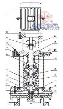
Structure diagram
 |
Serial Number |
name |
Serial Number |
name |
1 |
pump body |
11 |
coupling |
|
2 |
Tighten the bolt |
12 |
Connecting seat |
|
3 |
outer cylinder |
13 |
valve |
|
4 |
impeller |
14 |
mechanical seal |
|
5 |
Impeller sleeve |
15 |
axle |
|
6 |
shaft sleeve |
16 |
middle |
|
7 |
seal pad |
17 |
Shaft sleeve nut |
|
8 |
nut |
18 |
bearing shell |
|
9 |
Xiao |
19 |
Return pipe components |
|
10 |
electrical machinery |
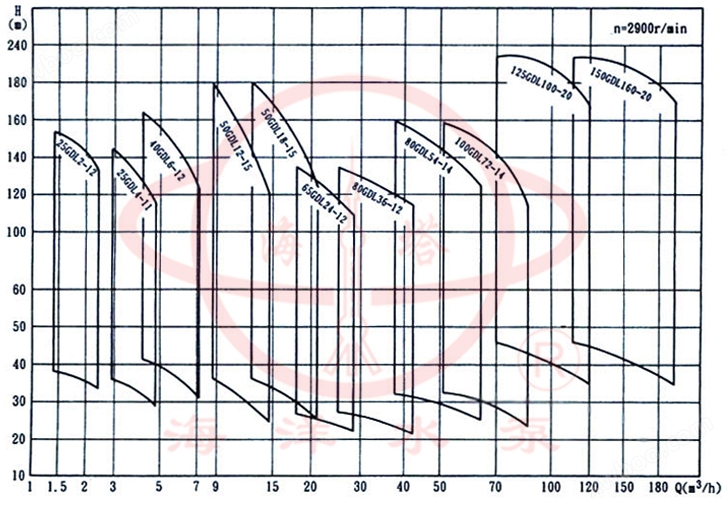
Spectrogram
 |
performance parameter
model |
series |
internet traffic |
lift |
rotational speed |
Motor Power |
efficiency |
Required cavitation allowance |
weight |
m3/h |
M |
r/min |
kw |
% |
NPSH |
KG |
||
25GDL2-12 |
3 |
2 |
36 |
2900 |
1.1 |
30 |
2.9 |
58 |
25GDL2-12 |
4 |
2 |
48 |
2900 |
1.1 |
30 |
2.9 |
62 |
25GDL2-12 |
5 |
2 |
60 |
2900 |
2 |
30 |
2.9 |
68 |
25GDL2-12 |
6 |
2 |
72 |
2900 |
2 |
30 |
2.9 |
72 |
25GDL2-12 |
7 |
2 |
84 |
2900 |
2 |
30 |
2.9 |
78 |
25GDL2-12 |
8 |
2 |
96 |
2900 |
2.2 |
30 |
2.9 |
82 |
25GDL2-12 |
9 |
2 |
108 |
2900 |
2 |
30 |
2.9 |
86 |
25GDL2-12 |
10 |
2 |
120 |
2900 |
3 |
30 |
2.9 |
98 |
25GDL2-12 |
11 |
2 |
132 |
2900 |
3 |
30 |
2.9 |
102 |
25GDL2-12 |
12 |
2 |
144 |
2900 |
3 |
30 |
2.9 |
|
25GDL2-12 |
13 |
2 |
156 |
2900 |
4 |
30 |
2.9 |
|
25GDL2-12 |
14 |
2 |
168 |
2900 |
4 |
30 |
2.9 |
|
25GDL2-12 |
15 |
2 |
180 |
2900 |
4 |
30 |
2.9 |
|
model |
series |
internet traffic |
lift |
rotational speed |
Motor Power |
efficiency |
Required cavitation allowance |
weight |
m3/h |
M |
r/min |
kw |
% |
NPSH |
KG |
||
25GDL4-11 |
3 |
4 |
33 |
2900 |
1.1 |
42 |
2.9 |
58 |
25GDL4-11 |
4 |
4 |
44 |
2900 |
1.5 |
42 |
2.9 |
65 |
25GDL4-11 |
5 |
4 |
55 |
2900 |
2.2 |
42 |
2.9 |
72 |
25GDL4-11 |
6 |
4 |
66 |
2900 |
2.2 |
42 |
2.9 |
76 |
25GDL4-11 |
7 |
4 |
77 |
2900 |
3 |
42 |
2.9 |
86 |
25GDL4-11 |
8 |
4 |
88 |
2900 |
3 |
42 |
2.9 |
90 |
25GDL4-11 |
9 |
4 |
99 |
2900 |
3 |
42 |
2.9 |
94 |
25GDL4-11 |
10 |
4 |
110 |
2900 |
4 |
42 |
2.9 |
110 |
25GDL4-11 |
11 |
4 |
121 |
2900 |
4 |
42 |
2.9 |
114 |
25GDL4-11 |
12 |
4 |
132 |
2900 |
4 |
42 |
2.9 |
|
25GDL4-11 |
13 |
4 |
143 |
2900 |
4 |
42 |
2.9 |
|
25GDL4-11 |
14 |
4 |
154 |
2900 |
5.5 |
42 |
2.9 |
|
25GDL4-11 |
15 |
4 |
165 |
2900 |
5.5 |
42 |
2.9 |
|
model |
series |
internet traffic |
lift |
rotational speed |
Motor Power |
efficiency |
Required cavitation allowance |
weight |
m3/h |
M |
r/min |
kw |
% |
NPSH |
KG |
||
40GDL6-12 |
3 |
6 |
36 |
2900 |
1.5 |
52 |
2.9 |
72 |
40GDL6-12 |
4 |
6 |
48 |
2900 |
2.2 |
52 |
2.9 |
78 |
40GDL6-12 |
5 |
6 |
60 |
2900 |
2.2 |
52 |
2.9 |
82 |
40GDL6-12 |
6 |
6 |
72 |
2900 |
3 |
52 |
2.9 |
92 |
40GDL6-12 |
7 |
6 |
84 |
2900 |
3 |
52 |
2.9 |
96 |
40GDL6-12 |
8 |
6 |
96 |
2900 |
4 |
52 |
2.9 |
112 |
40GDL6-12 |
9 |
6 |
108 |
2900 |
4 |
52 |
2.9 |
116 |
40GDL6-12 |
10 |
6 |
120 |
2900 |
4 |
52 |
2.9 |
120 |
40GDL6-12 |
11 |
6 |
132 |
2900 |
5.5 |
52 |
2.9 |
140 |
40GDL6-12 |
12 |
6 |
144 |
2900 |
5.5 |
52 |
2.9 |
|
40GDL6-12 |
13 |
6 |
156 |
2900 |
7.5 |
52 |
2.9 |
|
40GDL6-12 |
14 |
6 |
168 |
2900 |
7.5 |
52 |
2.9 |
|
40GDL6-12 |
15 |
6 |
180 |
2900 |
7.5 |
52 |
2.9 |
|
model |
series |
internet traffic |
lift |
rotational speed |
Motor Power |
efficiency |
Required cavitation allowance |
weight |
m3/h |
M |
r/min |
kw |
% |
NPSH |
KG |
||
50GDL12-15 |
2 |
12 |
30 |
2900 |
2.2 |
57 |
3.5 |
113 |
50GDL12-15 |
3 |
12 |
45 |
2900 |
3 |
57 |
3.5 |
129 |
50GDL12-15 |
4 |
12 |
60 |
2900 |
4 |
57 |
3.5 |
149 |
50GDL12-15 |
5 |
12 |
75 |
2900 |
5.5 |
57 |
3.5 |
181 |
50GDL12-15 |
6 |
12 |
90 |
2900 |
5.5 |
57 |
3.5 |
190 |
50GDL12-15 |
7 |
12 |
105 |
2900 |
7.5 |
57 |
3.5 |
204 |
50GDL12-15 |
8 |
12 |
120 |
2900 |
7.5 |
57 |
3.5 |
212 |
50GDL12-15 |
9 |
12 |
135 |
2900 |
11 |
57 |
3.5 |
265 |
50GDL12-15 |
10 |
12 |
150 |
2900 |
11 |
57 |
3.5 |
273 |
model |
series |
internet traffic |
lift |
rotational speed |
Motor Power |
efficiency |
Required cavitation allowance |
weight |
m3/h |
M |
r/min |
kw |
% |
NPSH |
KG |
||
50GDL18-15 |
2 |
18 |
30 |
2900 |
3 |
63 |
4.0 |
122 |
50GDL18-15 |
3 |
18 |
45 |
2900 |
4 |
63 |
4.0 |
142 |
50GDL18-15 |
4 |
18 |
60 |
2900 |
5.5 |
63 |
4.0 |
175 |
50GDL18-15 |
5 |
18 |
75 |
2900 |
7.5 |
63 |
4.0 |
189 |
50GDL18-15 |
6 |
18 |
90 |
2900 |
7.5 |
63 |
4.0 |
198 |
50GDL18-15 |
7 |
18 |
105 |
2900 |
11 |
63 |
4.0 |
252 |
50GDL18-15 |
8 |
18 |
120 |
2900 |
11 |
63 |
4.0 |
261 |
50GDL18-15 |
9 |
18 |
135 |
2900 |
15 |
63 |
4.0 |
280 |
50GDL18-15 |
10 |
18 |
150 |
2900 |
15 |
63 |
4.0 |
289 |
model |
series |
internet traffic |
lift |
rotational speed |
Motor Power |
efficiency |
Required cavitation allowance |
weight |
m3/h |
M |
r/min |
kw |
% |
NPSH |
KG |
||
65GDL24-12 |
2 |
24 |
24 |
2900 |
3 |
63 |
4.0 |
122 |
65GDL24-12 |
3 |
24 |
36 |
2900 |
4 |
63 |
4.0 |
142 |
65GDL24-12 |
4 |
24 |
48 |
2900 |
5.5 |
63 |
4.0 |
175 |
65GDL24-12 |
5 |
24 |
60 |
2900 |
7.5 |
63 |
4.0 |
189 |
65GDL24-12 |
6 |
24 |
72 |
2900 |
7.5 |
63 |
4.0 |
252 |
65GDL24-12 |
7 |
24 |
84 |
2900 |
11 |
63 |
4.0 |
261 |
65GDL24-12 |
8 |
24 |
96 |
2900 |
11 |
63 |
4.0 |
280 |
65GDL24-12 |
9 |
24 |
108 |
2900 |
15 |
63 |
4.0 |
289 |
65GDL24-12 |
10 |
24 |
120 |
2900 |
15 |
63 |
4.0 |
298 |
65GDL24-12 |
11 |
24 |
132 |
2900 |
15 |
63 |
4.0 |
317
|
65GDL24-12 |
12 |
24 |
144 |
2900 |
18.5 |
63 |
4.0 |
346 |
model |
series |
internet traffic |
lift |
rotational speed |
Motor Power |
efficiency |
Required cavitation allowance |
weight |
m3/h |
M |
r/min |
kw |
% |
NPSH |
KG |
||
80GDL36-12 |
2 |
36 |
24 |
2900 |
4 |
71 |
4.2 |
193 |
80GDL36-12 |
3 |
36 |
36 |
2900 |
5.5 |
71 |
4.2 |
227 |
80GDL36-12 |
4 |
36 |
48 |
2900 |
7.5 |
71 |
4.2 |
244 |
80GDL36-12 |
5 |
36 |
60 |
2900 |
11 |
71 |
4.2 |
292 |
80GDL36-12 |
6 |
36 |
72 |
2900 |
11 |
71 |
4.2 |
302 |
80GDL36-12 |
7 |
36 |
84 |
2900 |
15 |
71 |
4.2 |
322 |
80GDL36-12 |
8 |
36 |
96 |
2900 |
15 |
71 |
4.2 |
332 |
80GDL36-12 |
9 |
36 |
108 |
2900 |
18.5 |
71 |
4.2 |
365 |
80GDL36-12 |
10 |
36 |
120 |
2900 |
18.5 |
71 |
4.2 |
375 |
model |
series |
internet traffic |
lift |
rotational speed |
Motor Power |
efficiency |
Required cavitation allowance |
weight |
m3/h |
M |
r/min |
kw |
% |
NPSH |
KG |
||
80GDL54-14 |
2 |
54 |
28 |
2900 |
7.5 |
73 |
4.0 |
218 |
80GDL54-14 |
3 |
54 |
42 |
2900 |
11 |
73 |
4.0 |
267 |
80GDL54-14 |
4 |
54 |
56 |
2900 |
15 |
73 |
4.0 |
287 |
80GDL54-14 |
5 |
54 |
70 |
2900 |
18.5 |
73 |
4.0 |
320 |
80GDL54-14 |
6 |
54 |
84 |
2900 |
18.5 |
73 |
4.0 |
330 |
80GDL54-14 |
7 |
54 |
98 |
2900 |
22 |
73 |
4.0 |
373 |
80GDL54-14 |
8 |
54 |
112 |
2900 |
30 |
73 |
4.0 |
400 |
80GDL54-14 |
9 |
54 |
126 |
2900 |
30 |
73 |
4.0 |
421 |
80GDL54-14 |
10 |
54 |
140 |
2900 |
37 |
73 |
4.0 |
432 |
model |
series |
internet traffic |
lift |
rotational speed |
Motor Power |
efficiency |
Required cavitation allowance |
weight |
m3/h |
M |
r/min |
kw |
% |
NPSH |
KG |
||
100GDL72-14 |
2 |
72 |
28 |
2900 |
11 |
73 |
4.5 |
276 |
100GDL72-14 |
3 |
72 |
42 |
2900 |
15 |
73 |
4.5 |
298 |
100GDL72-14 |
4 |
72 |
56 |
2900 |
18.5 |
73 |
4.5 |
336 |
100GDL72-14 |
5 |
72 |
70 |
2900 |
22 |
73 |
4.5 |
381 |
100GDL72-14 |
6 |
72 |
84 |
2900 |
30 |
73 |
4.5 |
453 |
100GDL72-14 |
7 |
72 |
98 |
2900 |
30 |
73 |
4.5 |
466 |
100GDL72-14 |
8 |
72 |
112 |
2900 |
37 |
73 |
4.5 |
493 |
100GDL72-14 |
9 |
72 |
126 |
2900 |
37 |
73 |
4.5 |
582 |
100GDL72-14 |
10 |
72 |
140 |
2900 |
45 |
73 |
4.5 |
595 |
model |
series |
internet traffic |
lift |
rotational speed |
Motor Power |
efficiency |
Required cavitation allowance |
weight |
m3/h |
M |
r/min |
kw |
% |
NPSH |
KG |
||
100GDL100-20 |
2 |
108 |
40 |
2900 |
18.5 |
74 |
4.5 |
292 |
100GDL100-20 |
3 |
108 |
60 |
2900 |
30 |
74 |
4.5 |
430 |
100GDL100-20 |
4 |
108 |
80 |
2900 |
37 |
74 |
4.5 |
463 |
100GDL100-20 |
5 |
108 |
100 |
2900 |
45 |
74 |
4.5 |
555 |
100GDL100-20 |
6 |
108 |
120 |
2900 |
55 |
74 |
4.5 |
640 |
100GDL100-20 |
7 |
108 |
140 |
2900 |
75 |
74 |
4.5 |
840 |
100GDL100-20 |
8 |
108 |
160 |
2900 |
75 |
74 |
4.5 |
855 |
100GDL100-20 |
9 |
108 |
180 |
2900 |
90 |
74 |
4.5 |
870 |
100GDL100-20 |
10 |
108 |
200 |
2900 |
90 |
74 |
4.5 |
955 |
model |
series |
internet traffic |
lift |
rotational speed |
Motor Power |
efficiency |
Required cavitation allowance |
weight |
m3/h |
M |
r/min |
kw |
% |
NPSH |
KG |
||
125GDL100-20 |
2 |
108 |
40 |
2900 |
18.5 |
74 |
4.5 |
292 |
125GDL100-20 |
3 |
108 |
60 |
2900 |
30 |
74 |
4.5 |
430 |
125GDL100-20 |
4 |
108 |
80 |
2900 |
37 |
74 |
4.5 |
463 |
125GDL100-20 |
5 |
108 |
100 |
2900 |
45 |
74 |
4.5 |
555 |
125GDL100-20 |
6 |
108 |
120 |
2900 |
55 |
74 |
4.5 |
640 |
125GDL100-20 |
7 |
108 |
140 |
2900 |
75 |
74 |
4.5 |
840 |
125GDL100-20 |
8 |
108 |
160 |
2900 |
75 |
74 |
4.5 |
855 |
125GDL100-20 |
9 |
108 |
180 |
2900 |
90 |
74 |
4.5 |
870 |
125GDL100-20 |
10 |
108 |
200 |
2900 |
90 |
74 |
4.5 |
955 |
model |
series |
internet traffic |
lift |
rotational speed |
Motor Power |
efficiency |
Required cavitation allowance |
weight |
m3/h |
M |
r/min |
kw |
% |
NPSH |
KG |
||
150GDL160-20 |
2 |
160 |
40 |
2900 |
30 |
78 |
4.5 |
422 |
150GDL160-20 |
3 |
160 |
60 |
2900 |
37 |
78 |
4.5 |
452 |
150GDL160-20 |
4 |
160 |
80 |
2900 |
55 |
78 |
4.5 |
613 |
150GDL160-20 |
5 |
160 |
100 |
2900 |
75 |
78 |
4.5 |
820 |
150GDL160-20 |
6 |
160 |
120 |
2900 |
75 |
78 |
4.5 |
836 |
150GDL160-20 |
7 |
160 |
140 |
2900 |
90 |
78 |
4.5 |
922 |
model |
series |
internet traffic |
lift |
rotational speed |
Motor Power |
efficiency |
Required cavitation allowance |
weight |
m3/h |
M |
r/min |
kw |
% |
NPSH |
KG |
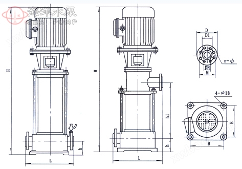
Installation size
 |
|||||||
model |
H1
|
L |
B |
4-φd1
|
Imported flange (J) |
||
DN
|
N-φD2
|
φD |
|||||
25GDL |
60 |
300 |
200 |
4-φ18 |
25 |
4-φ14 |
85 |
40GDL |
80 |
360 |
235 |
4-φ18 |
40 |
4-φ18 |
110 |
50GDL |
100 |
360 |
235 |
4-φ18 |
50 |
4-φ18 |
125 |
65GDL |
110 |
360 |
235 |
4-φ18 |
65 |
4-φ18 |
145 |
80GDL |
130 |
420 |
300 |
4-φ18 |
80 |
8-φ18 |
160 |
100GDL |
160 |
520 |
350 |
4-φ18 |
100 |
8-φ18 |
180 |
125GDL |
160 |
500 |
400 |
4-φ18 |
125 |
8-φ18 |
210 |
150GDL |
180 |
600 |
400 |
4-φ18 |
150 |
8-φ22 |
245 |
Installation instructions
1. The weight of the pipeline should not be borne on the pump during installation, otherwise it is easy to damage the pump;
2. The pump and motor are integral structures that have been calibrated by the manufacturer before leaving the factory, so there is no need to adjust them during installation, making it very convenient;
3. Before installing the water pump, carefully check whether there are any hard objects (such as stones, iron sand, etc.) in the flow channel that affect the operation of the water pump to avoid damaging the overcurrent components during the operation of the water pump;
4. The foundation bolts must be tightened before installation, and the pump should be checked for looseness at regular intervals to prevent severe vibration during pump start-up and affect its performance;
5. For the convenience of maintenance and safety of use, a regulating valve should be installed on the inlet and outlet pipelines of the pump, and a pressure gauge should be installed near the inlet and outlet of the pump. For high head, in order to prevent water hammer, a check valve should also be installed in front of the outlet gate valve to cope with sudden power outages and other power loss accidents, so as to ensure that the water pump operates in good working conditions and increase its service life;
6. When the water pump is used in suction applications, it should be equipped with a bottom valve, and the inlet pipeline should not have too many bends. At the same time, there should be no water or air leakage to avoid affecting the suction performance of the water pump;
7. To prevent impurities from entering the pump and blocking the flow path, a filter should be installed in front of the pump inlet to improve performance;
8. Before installing the pipeline, rotate the rotor components of the water pump without any friction sound or jamming phenomenon. Otherwise, the pump should be disassembled to check the cause.
Start and Stop
Preparation before starting
1. Pull and rotate the coupling by hand, and the impeller should have no jamming or grinding phenomenon, and rotate flexibly;
2. Open the inlet valve, open the exhaust valve to fill the entire pump chamber with liquid, and then close the exhaust nozzle;
3. When transporting hot liquids, preheating should be carried out before starting, with a heating rate of 50 ℃/h. The preheating of the pump is achieved by continuously circulating the transported liquid to ensure uniform heating of all parts;
4. The pump should be manually rotated a few times to allow lubricating water to enter the mechanical seal end face;
5. Tap the motor to confirm if the direction of rotation is correct.
Start up and operation
1. Fully open the inlet valve and close the outlet pipeline valve;
2. Connect the power supply, gradually open the valve on the discharge pipeline and adjust it to the desired working condition when the GDL type booster multi-stage pump reaches normal speed;
3. Pay attention to the instrument readings and check the leakage of the shaft seal. Normally, the mechanical seal leaks at a rate of 3 leaks per minute. Check that the temperature at the motor and bearings is ≤ 70 ℃. If any abnormal situation is found, it should be dealt with in a timely manner.
park
1. Gradually close the valve of the discharge pipeline;
2. Close the inlet valve;
3. If the ambient temperature is below 0 ℃. The liquid inside the pump should be drained completely to prevent the water pump from freezing and cracking;
4. If the pump is not used for a long time, it should be disassembled, cleaned, packaged and stored.
maintenance
Maintenance and upkeep during operation
1. The inlet pipeline must be highly sealed and must not leak or leak water;
2. Prohibit long-term operation of water pumps under cavitation conditions;
3. Prohibit long-term operation of motor overcurrent when the water pump operates under high flow conditions;
4. Regularly check the motor current value during the operation of the water pump, and try to operate the pump within the design operating range as much as possible;
5. The water pump should be monitored by a dedicated person during operation to prevent accidents;
6. The bearings of the water pump should be lubricated every 500 hours of operation;
7. After long-term operation of the water pump, due to mechanical wear, the noise and vibration of the unit increase. It should be stopped for inspection, and if necessary, vulnerable parts and bearings can be replaced. The overhaul period of the unit is generally one year.
Maintenance and upkeep of mechanical seals
1. Mechanical seal lubricant should be clean and free of solid particles;
2. Mechanical sealing is strictly prohibited from working under dry grinding conditions;
3. Before starting, the pump (motor) should be turned a few times to avoid mechanical seal breakage and damage caused by sudden starting.
Fault causes and troubleshooting methods
Fault phenomenon |
Possible causes |
Troubleshooting |
||||||||||||
|
1. The water pump is not producing water
|
|
|
||||||||||||
|
2. Insufficient water pump flow
|
|
|
||||||||||||
|
3. Excessive power
|
|
|
||||||||||||
|
4. Noise vibration
|
|
|
||||||||||||
|
5. Motor overheating
|
|
|
||||||||||||
|
6. Water pump leakage
|
|
|
Online inquiry
-
Contacts
-
Company
-
Telephone
-
Email
-
WeChat
-
Verification Code
-
Message Content
-