
VIP member
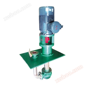
FY type explosion-proof, corrosion-resistant, wear-resistant submersible pump
Release time: 2017-12-22 16:16:46 Brand: Longyang Pump Valve model: FY type Flow range: 15-54m3/h Head range: 15m Operating temperature: -15 ℃ -105 ℃
Product details
1 Overview of FY Explosion proof, Corrosion resistant and Wear resistant Submersible Pump
The explosion-proof, corrosion-resistant, and wear-resistant submersible pump is a new type of pump produced by our unit based on the improved technology and design of traditional corrosion-resistant submersible pumps; The submersible pump eliminates the mechanical seal commonly used in other submersible pumps and adopts a unique structure of impeller, making the pump efficient, energy-saving, leak free, and long-lasting, thus widely used in industries such as petroleum, chemical, pharmaceutical, papermaking, metallurgy, and sewage treatment.

FY type explosion-proof, corrosion-resistant, wear-resistant submersible pump
2 Design Features of FY Explosion proof, Corrosion resistant and Wear resistant Submersible Pump Product
1. The pump is a vertical submersible pump with a beautiful appearance, which can be directly installed on the storage container of the conveyed medium without additional land occupation, thereby reducing infrastructure investment;
2. Cancelled the mechanical seal, solved the problem of frequent maintenance for other submersible pumps due to the easy wear and tear of mechanical seals, saved the operating costs of the pump, and improved work efficiency;
3. Adopting a unique centrifugal double balanced impeller for conveying clean media without solid particles, with extremely low vibration noise and high efficiency; Adopting an open double balanced impeller for conveying liquids with solid particles and short fibers that are not clean, running smoothly and without blockage;
3 The main purpose of FY type explosion-proof, corrosion-resistant and wear-resistant submersible pump is
FY type explosion-proof, corrosion-resistant, wear-resistant submersible pump can transport media such as acid, alkali, salt, oil, beverages, etc. It is widely used in chemical, petrochemical, fine chemical, dye chemical, instrumentation, light industry, metallurgy, textile, environmental protection, water treatment, medicine, food and other departments.
4 The significance of FY type explosion-proof, corrosion-resistant and wear-resistant submersible pump model

5 FY Explosion proof, Corrosion resistant and Wear resistant Submersible Pump Structure and Installation Dimensional Drawing

Structural diagram of FY type corrosion-resistant and wear-resistant submersible pump

Installation dimensions of FY type corrosion-resistant and wear-resistant submersible pump
6 Performance Table of FY Explosion proof, Corrosion resistant and Wear resistant Submersible Pump Parameters
| model | Pump rated speed n=2900r/min | Pump rated speed n=1450r/min | ||||
| Traffic Q (m3/h) |
Head H (m) |
Motor power (KW) |
Traffic Q (m3/h) |
head (m) |
Motor power (KW) |
|
| 25FY-25 | 3.6 | 25 | 2.2 | 1.6 | 6 | 0.75 |
| 25FY-41 | 3.6 | 41 | 4 | 1.6 | 10 | 1.5 |
| 25FY-50 | 3.2 | 50 | 5.5 | 1.6 | 12.5 | 1.5 |
| 25FY-80 | 3.2 | 80 | 11 | 1.6 | 20 | 2.2 |
| 40FY-16 | 7.2 | 16 | 2.2 | 3.6 | 4 | 1.1 |
| 40FY-26 | 7.2 | 26 | 3 | 3.6 | 5 | 1.1 |
| 40FY-40 | 7.2 | 40 | 4 | 3.6 | 10 | 1.5 |
| 40FY-50 | 6.3 | 50 | 5.5 | 3.2 | 12.5 | 1.5 |
| 40FY-80 | 6.3 | 80 | 11 | 3.2 | 20 | 2.2 |
| 50FY-25 | 14.4 | 25 | 4 | 7.2 | 6 | 1.5 |
| 50FY-40 | 14.4 | 40 | 7.5 | 7.2 | 10 | 2.2 |
| 50FY-50 | 12.5 | 50 | 7.5 | 6.3 | 12.5 | 2.2 |
| 50FY-80 | 12.5 | 80 | 15 | 6.3 | 20 | 3 |
| 65FY-25 | 28.8 | 25 | 5.5 | 14 | 6 | 1.5 |
| 65FY-40 | 28.8 | 40 | 11 | 14 | 10 | 3 |
| 65FY-50 | 25 | 50 | 11 | 12.5 | 12.5 | 3 |
| 65FY-80 | 25 | 80 | 18.5 | 12.5 | 20 | 3 |
| 65FY-125 | 25 | 125 | 30 | 12.5 | 32 | 5.5 |
| 80FY-15 | 54 | 15 | 5.5 | 27 | 4 | 0.75 |
| 80FY-24 | 54 | 24 | 11 | 27 | 6 | 1.1 |
| 80FY-38 | 54 | 38 | 15 | 27 | 9 | 1.5 |
| 80FY-50 | 50 | 50 | 22 | 25 | 12.5 | 2.2 |
| 80FY-80 | 50 | 80 | 30 | 25 | 20 | 4 |
| 80FY-125 | 50 | 125 | 45 | 25 | 32 | 7.5 |
| 100FY-23 | 100 | 23 | 11 | 50 | 5 | 2.2 |
| 100FY-37 | 100 | 37 | 15 | 50 | 9 | 3 |
| 100FY-50 | 100 | 50 | 30 | 50 | 12.5 | 4 |
| 100FY-80 | 100 | 80 | 45 | 50 | 20 | 7.5 |
| 100FY-125 | 100 | 125 | 75 | 50 | 32 | 11 |
| 125FY-50 | 200 | 50 | 45 | 100 | 12.5 | 7.5 |
| 125FY-80 | 200 | 80 | 75 | 100 | 20 | 15 |
| 125FY-125 | 200 | 125 | 132 | 100 | 32 | 18.5 |
| 150FY-20 |
|
|
|
200 | 20 | 30 |
| 150FY-32 |
|
|
|
200 | 32 | 45 |
| 150FY-50 |
|
|
|
200 | 50 | 55 |
| 200FY-20 |
|
|
|
400 | 20 | 45 |
| 200FY-32 |
|
|
|
400 | 32 | 75 |
| 200FY-50 |
|
|
|
400 | 50 | 90 |
6 FY type explosion-proof, corrosion-resistant, wear-resistant submersible pump for loading, unloading, installation, starting, and operation
1. The disassembly sequence of the pump
(1) Close the gate valve in the discharge pipeline, remove the connecting bolts of the upper half flange of the discharge pipeline, and dismantle a section of the pipeline whose length does not hinder the start of the pump.
(2) Loosen the connecting bolts between the motor frame and the bearing box, and lift off the motor.
(3) Loosen the connecting bolts between the bottom plate and the container, and lift the pump out of the container along with the bottom plate. And clean it with clean water. To prevent air oxidation and corrosion, it should be dismantled immediately.
(4) Remove the pump cover, unscrew the impeller nut (left turn), and remove the impeller.
(5) Remove the pump body, take out the guide bearing, lower protective shaft sleeve, and flat key.
(6) Remove the half flange of the outlet pipe connected to the bottom plate.
(7) Remove the middle connecting pipe. (If there is an intermediate guide bearing, remove it together)
(8) Remove the bottom plate, take off the pump coupling and key, remove the bearing cover and packing cover, and take out the rotor body.
(9) Unscrew the round nut and remove the ball bearing and upper bushing.
The assembly sequence of the pump is opposite to the disassembly sequence. When assembling rotor components, the radial runout of the sealing ring and the outer circumference of the shaft sleeve should be checked and not exceed the values listed in the table.
3. Installation:
(1) After the pump is assembled, rotate the coupling to see if it rotates flexibly, check for any metal friction sounds, and prepare tools and lifting machinery.
(2) Check the concentricity between the pump shaft and motor shaft. The difference between the outer circles of the two couplings should not exceed 0.1 millimeters, and the gap between the end faces of the two couplings should not exceed 0.3 millimeters per week.
(3) The guide bearing should be able to be immersed in liquid, otherwise an appropriate amount of liquid should be drawn out from the outlet pipeline to lubricate the guide bearing and prevent dry wear damage.
(4) When there may be debris falling into the container in the chemical process system, to prevent damage to the pump body from debris, a required form of fence net can be installed at the suction point.
(5) The distance from the suction port of the pump to the bottom of the container should be 1.5 to 2 times the suction diameter, and there should be no less than 2.5 parts around it. For small diameters, the larger value should be taken, and for large diameters, the smaller value should be taken.
(6) The outlet pipeline of the pump should be supported by a separate bracket, and its weight should not be added to the pump body.
(7) After installation, it is necessary to check whether the nuts of each component are tightened, and rotate the coupling to see if it rotates flexibly before assembling the pump motor on the container. After installation, check again.
4. Start and stop:
(1) Check the bearing chamber to maintain a certain amount of clean butter. Usually, it is advisable to fill the oil chamber with 1/2 to 1/3. Avoid excessive temperature rise of bearings during operation. At the same time, apply an appropriate amount of butter lubrication to the filling area.
(2) Rotate the coupling and check for uneven weight. Otherwise, the cause must be identified and eliminated before operation.
(3) Check the direction of rotation of the electric motor to match the specified rotation direction of the pump.
(4) Close the gate valve and pressure gauge on the outlet pipeline. If cooling is required at the sealing point of the packing, circulating cooling water should be used.
(5) Start the motor, turn on the pressure gauge, slowly close the outlet gate valve, then stop the motor and turn off the pressure gauge.
(6) To shut down normally, slowly close the outlet gate valve first, then stop the motor and turn off the pressure gauge.
(7) If the pump is parked or not used for a long time, it should be removed from the container, cleaned, reinstalled, refueled and stored.
5. Operation:
(1) The bearing temperature should not exceed 75 ℃, and there should be an appropriate amount of butter inside the bearing box.
(2) Always pay attention to ensuring the purity of the lubricating oil.
(3) If the following faults occur during the operation of the pump, it should be stopped immediately and repaired.
Online inquiry
-
Contacts
-
Company
-
Telephone
-
Email
-
WeChat
-
Verification Code
-
Message Content
-