
VIP member
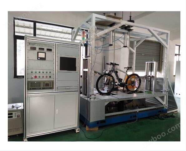
Electric assisted bicycle whole vehicle testing system
Host Introduction: This system is easy to test and has a beautiful appearance. Fast testing speed. Suitable for type testing in electric vehicle facto
Product details
This system is designed in accordance with EU standards (BS EN 15194:2009), national standards (GB/T 24156-2009), (GB/T 24157-2009), (GB/T 24158-2009) and other standards. The testing operation is convenient and aesthetically pleasing. Fast testing speed. Suitable for type testing in electric vehicle factories.
1 List of Power Machines for Electric Bicycles Chassis (as shown in the diagram)
|
Serial Number
|
name
|
brand
|
model
|
unit
|
quantity
|
notes
|
|
1
|
Mechanical bench
|
Weig
|
3000*2000*2600mm
|
only
|
1
|
|
|
2
|
drum
|
Weig
|
Steel with a diameter of 460mm
|
only
|
3
|
|
|
3
|
Torque sensor and coupling
|
tricrystal
|
JN338-100AE
|
only
|
1
|
|
|
4
|
Torque sensor and coupling
|
tricrystal
|
JN338-100AE
|
only
|
1
|
|
|
5
|
Front and rear wheel synchronous structure
|
Weig
|
Synchronous wheel with pulley
|
cover
|
1
|
|
|
6
|
Front and rear wheel clamping structure
|
Weig
|
Non standard
|
cover
|
1
|
|
|
7
|
Driver simulated mass loading
|
Weig
|
Handlebar and saddle 100KG
|
cover
|
1
|
|
|
8
|
Simulate the pneumatic brake structure of left and right brake levers
|
Weig
|
Quality 20KG * 2
|
cover
|
1
|
|
|
9
|
Crankshaft servo drive motor mechanism
|
Panasonic
|
Servo motor+reducer+
coupling
|
cover
|
1
|
|
|
10
|
Three dimensional adjustment mechanism for crankshaft base plate
|
Weig
|
Up, down, back, left, right, front and back adjustment
|
cover
|
1
|
|
|
11
|
Rear axle loading servo drive motor mechanism
|
Panasonic
|
Servo motor+magnetic powder brake+coupling
|
cover
|
1
|
|
|
12
|
pneumatic components
|
SMC
|
Barometer and ¢ 30 cylinder
|
cover
|
1
|
|
|
13
|
Safety device
|
|
2-channel reconnaissance
|
cover
|
1
|
|
|
14
|
Power distribution cabinet
|
Weig
|
Standard cabinet
|
only
|
1
|
|
|
15
|
DC power supply cabinet
|
Weig
|
DCS6050 60V,50A
|
only
|
1
|
|
|
16
|
System control cabinet
|
Weig
|
Standard cabinet
|
only
|
1
|
|
|
17
|
Paperless recorder
|
Pangu
|
VX5308
|
only
|
1
|
|
|
18
|
Crankshaft servo controller
|
Panasonic
|
2.2KW,
|
only
|
1
|
|
|
19
|
Rear wheel load servo system
|
Panasonic
|
2.2KW
|
cover
|
1
|
|
|
20
|
Industrial control computer and Panasonic PLC acquisition card
|
News research
|
Host, 17 inch LCD/
HP1020 laser printer
|
cover
|
1
|
|
|
21
|
Control software and testing software
|
Weig
|
Specially designed for chassis power testing
|
individual
|
1
|
|
IIMain control cabinet:
Use vertical cabinets; Built in computer monitor, industrial computer, mouse and keyboard; The panel is equipped with a single-phase AC power meter, power switch, and emergency stop button; Internally installed are PLC controllers, DC parameter measurement modules, etc.
IIIPower distribution cabinet:
Use vertical cabinets; There are three voltmeters installed on the panel, namely phase A, phase B, and phase C at the three-phase incoming terminals of the power distribution cabinet; Internally, there is mainly a 2.2kW Panasonic servo drive unit, a 3kW servo drive controller, reactors, transformers, etc.
The main function of this cabinet is to provide power for the crankshaft loading motor, drum loading motor, and cooling fan, and control their movement modes.
4DC power cabinet:
Use vertical cabinets; There is a DC voltmeter and a DC ammeter installed on the panel, mainly used to display the output status of the current DC stabilized power supply. Internally, there is mainly a DCS6050/60V, 50A DC stabilized power supply and some DC main circuit switching devices.
The main function of this cabinet is to equip the testing vehicle with an external DC power supply instead of the battery pack for the testing vehicle; Capable of switching between battery pack and external DC power supply.
5Testing Platform:
The testing platform is mainly equipped with front drum, rear drum, drum loading variable frequency motor, crankshaft loading motor, 2 JN338-200AE torque and speed sensors, 1 reducer, several photoelectric switches, cooling fan, etc; The platform is equipped with counterweight weights, which are placed on the vehicle seat cushion, footrest, and handlebars to simulate the driver's mass; There is also a pneumatic device on it, used for braking the front and rear wheels of the vehicle; Vehicle fixing device and wheel fixing device are used to keep the vehicle stable during the testing process, ensuring that the front and rear wheels do not deviate or leave the drum. There is a synchronous belt between the front and rear drums, which can achieve the function of single rear drum rotation loading and simultaneous rotation loading of the front and rear drums.
This platform is mainly used for placing test vehicles, collecting and measuring the output speed and torque of the driving wheels of the test vehicles through various sensors; The input speed and torque of the crankshaft; Monitor battery pack temperature, etc. The three-phase servo motor on the testing platform is used to provide driving assistance to the drum load simulation vehicle while driving on the road; Panasonic servo motors are used to load the crankshaft and simulate the driver's foot pedal power. The cooling fan installed at the front column of the testing platform is used to track the vehicle speed, provide corresponding cooling air force, and prevent excessive temperature of the wheels and other components.
Note: Please refer to the structural plan for the dimensions and external specifications of the cabinet!
System testing items and testing sequence:
The detailed testing content of each testing item is as follows:
1Power control:The test content includes front pedaling, brake power-off, stop pedaling, rear pedaling, and maximum designed assist speed.
Figure 1
Test method:
On the testing platform, the motor-driven wheels can be spun and simulated ground driving can be used for testing.
Load the crankshaft and simulate the pedaling of a rider's foot; Only when the foot pedals forward, electric assistance is provided, and the motor has a load current or torque output to the wheels.
When stepping backwards, there should be no electrical assistance. Or when stepping backwards, there is no load current point or torque output to the wheels.
The test vehicle is driven with assistance, and the system automatically controls the pneumatic device to brake the vehicle. The assistance electric device will automatically cut off or the current will decrease until it is completely powered off.
(The above tests should be conducted at 90% of the power-off speed of the test vehicle)
Make the test vehicle reach the maximum design assist speed, at which point the vehicle's power output or assist should gradually decrease until it is completely powered off. The increase and decrease of electric assistance should gradually and steadily proceed.
During the above testing process, the system will automatically test the vehicle's speed, test time, input current of the power assist motor or output torque of the driving wheels, distance, etc.
2Activate the power assist mode (if the vehicle does not have this function or is not authorized, this project does not need to be tested):Activate the assist mode during cycling, parking, and pushing.
Figure 2
Test method:
Load the crankshaft to reach 80% of the maximum assist speed of the test vehicle, then remove the crankshaft driving force and activate the assist mode to test whether the vehicle can maintain the design speed of 6km/h or below; Then turn off the power assist mode and check if the vehicle speed can return to 0km/h; After the vehicle stops, restart the assist mode and confirm that the current drops to or below the no-load current point; Then the dynamometer simulates the speed of the vehicle when it is pushed forward, and activates the assist mode, maintaining it for 1 minute to confirm that the speed is equal to or lower than 6km/h.
During the above test process, the system will automatically measure the speed of the test vehicle, test time, input current of the power assist motor, or output torque of the driving wheels.
Note: Vehicles without authorization or this function do not require measurement.
3Maximum speed:
Fig 3
Test method:
Place the test vehicle on the chassis dynamometer, simulate the driving assistance of the vehicle on the road with a drum, and operate the test vehicle at the highest speed on the chassis dynamometer; Directly read the vehicle speed. Conduct three consecutive tests, with the maximum speed being the average of the speeds measured during the three tests. And the difference between the lowest and highest values of the average vehicle speed measured in each test shall not exceed 3% of the lowest value, otherwise additional tests should be conducted to eliminate values that are more scattered.
During the above experiment, the system will automatically measure the speed of the test vehicle.
4Startup performance:The test content includes startup time and startup acceleration.
Figure 4
Test method:
After clamping the test vehicle, apply the rated torque force to the crankshaft at 0 vehicle speed to accelerate the test vehicle rapidly and start timing; At the same time, the drum dynamometer outputs simulated resistance torque with a 0-second delay, and directly reads the travel time of 30m, 100m, 200m, and 400m (distance can be set). Conduct three consecutive experiments. During this process, it is also necessary to record the time when the vehicle reaches its maximum speed, which is recorded as the start time.
Start acceleration calculation:
According to the above experimental method, calculate the average measurement time, and use equation (1) to calculate the acceleration from the starting point to each punctuation point, with the value accurate to one decimal place.
………………………(1)
In the formula:
A - Acceleration, unit m/s ²;
S - the distance from the starting point to each punctuation point, in meters;
T - the time from the starting point to each punctuation point, in seconds.
During the above experimental process, the system will automatically measure the speed, acceleration time, distance, etc. of the test vehicle.
5Climbing performance:Climbing at a fixed speed and slope.
Figure 5
Test method:
Constant speed climbing: Place the test vehicle on the chassis dynamometer, set the chassis dynamometer to constant speed control mode, and let the chassis dynamometer reverse the vehicle to the set speed. After the speed stabilizes, apply the rated torque force to the crankshaft to accelerate the test vehicle rapidly. After the test vehicle stabilizes again, record the output power of the test vehicle, and calculate the maximum climbing angle at this speed according to the following formula.
………………………(2)
………………………(3)
………………(4)
………………(5)
In the formula:
——Forward power, unit W;
——Simulated load parameters of chassis dynamometer, unit: kg;
——Set speed in km/h;
——Test the output power of the vehicle climbing during rapid acceleration;
——Overcoming the decline in power;
——Test mass, unit: kg;
——Climbing angle, unit: °;
Fixed slope climbing: Set the climbing load coefficient of the chassis dynamometer based on the climbing angle. After the test vehicle starts, accelerate rapidly to reach a stable value above the set speed. If the test vehicle cannot reach the set speed within 30 seconds after starting, stop the vehicle and reduce the climbing load coefficient of the chassis dynamometer (i.e. reduce the climbing angle) before conducting the test.
During the above experimental process, the system will automatically measure the power, speed, load, slope, mass, etc. of the test vehicle.
6Sliding performance:Sliding distance.
Figure 6
Test method:
Place the test vehicle on the chassis dynamometer and simulate the driving resistance of the vehicle on the road using a drum; The crankshaft servo loading motor loads the crankshaft of the test vehicle, allowing the test vehicle to run at a set speed and stabilize on the chassis dynamometer; Then stop the crankshaft loading motor and cut off the power circuit of the assist motor at the same time, allowing the wheels of the test vehicle to rotate freely until the vehicle stops due to driving resistance. The distance of free sliding of the vehicle during this section is measured as the sliding distance.
During the above experiment, the system will automatically measure the speed and sliding distance of the test vehicle.
7Vehicle efficiency:
Figure 7
Test method:
Place the test vehicle on the drum for testing and conduct the test for a period of time. Vehicle output power=Test torque x Test speed ÷ 9.55+Power absorbed by the dynamometer drum.
Input power: It is the sum of the power of the crankshaft loaded on the test vehicle and the output power of the DC power supply or battery. The power of the DC part is calculated by the AD sampling of the PLC.
Vehicle efficiency=Test vehicle output power ÷ Input power × 100%
During the above experimental process, the system will automatically measure the input power and output power of the test vehicle.
8Range:
Figure 8
Test method:
The battery is fully discharged and charged, and the amount of electricity consumed by the power grid is measured
Perform driving range according to cyclic or constant speed method
Recharge the power battery to its original capacity and measure the amount of electricity consumed by the power grid
Calculate energy consumption based on the mileage and recharge amount.
Calculation of energy consumption: C=E/D C energy consumption rate. The power grid capacity for recharging E. D is the total mileage during the trial period.
Evaluation of driving range and energy consumption rate.
Formula: Equivalent driving range D Equivalent=aD * D Operating condition+(1-aD) D Constant speed
Equivalent energy consumption rate: C equivalent=aC * C working condition+(1-aC) C constant velocity
AC is set to 0.6; AD is set to 0.6
Test termination condition: a) The vehicle undervoltage protection device is activated. b) At a constant speed, the driving speed cannot reach 70% of the designed maximum speed.
During the above experimental process, the system will automatically measure the vehicle speed, battery pack charging capacity, driving distance, etc. of the test vehicle.
Note: The software interface and operation during the experiment are detailed in the software plan!
System measurement parameters:
|
parameter
|
torque
(JN338)
|
rotational speed
(JN338)
|
voltage
DC
|
electric current
DC
|
||
|
drum
|
Crankshaft
|
drum
|
Crankshaft
|
|||
|
range
|
200N.m
|
200N.m
|
4000rpm
|
4000rpm
|
60V
|
50A
|
|
accuracy
|
0.5%
|
0.5%
|
0.2%
|
0.2%
|
0.5%
|
0.5%
|
Main configuration:
|
name
|
Model/Main Specifications
|
|
'Drum' torque sensor
|
JN338-100AE/100N.m
|
|
'Crankshaft' torque sensor
|
JN338-200AE/200N.m
|
|
'Drum' load motor
|
MGME302GGG/3kW Panasonic servo motor
Rated torque: 28.7N.m/synchronous speed: 750rpm
|
|
'Crankshaft' loading motor
|
MGME302GGG/3kW Panasonic servo motor
Rated torque: 28.7N.m/rated speed: 1000rpm
|
|
'Drum' load servo controller
|
Panasonic MFDHTB3A2 transmission unit
Four quadrant working mode
|
|
'Crankshaft' servo controller
|
Panasonic MFDHTB3A2
|
|
'Crankshaft' reducer
|
BH150-L1-7-B1-D1-S7
Rated output torque: 200N. m; Rated input speed: 3000rpm; Reduction ratio: 1/7
|
1. Photoelectric switch: There are three photoelectric switches, namely the front and rear drums and the two sides of the platform.
The photoelectric switches at the front and rear drums are reflective photoelectric sensors, which mainly detect whether the test vehicle is placed on the drum and whether the wheel position is correct; When the sensor does not detect the wheels of the tested vehicle, the system cannot perform the test operation. If the wheels of the vehicle deviate from the correct position during the testing process, the system will also stop the test.
The photoelectric switches on both sides of the test bench are light curtain type photoelectric sensors, which mainly function to prevent on-site personnel from entering the test bench and causing accidents during the testing process of the system; In the untested state of the system, this light curtain has no effect and only has a corresponding effect during the system testing process. When triggered, the system will stop testing.
2. Cooling fan: mainly used for heat dissipation of wheels and motors.
The placement position of the cooling fan is tentatively set in front of the test vehicle. Its working mode is to automatically start the fan to dissipate heat from the vehicle's wheels and other parts during various experiments. When the system stops testing, the fan will also automatically stop working.
3. Touch screen: mainly enables customers to obtain real-time basic information about the system and the tested vehicle at the on-site testing platform.
These two instruments are installed on the bench, and the main control on the touch screen is the on-site clamping device. During the testing process, basic information such as motor current and voltage can be monitored.
4. Electrical parameter testing methods and technical parameters
Technical parameters:
|
Measurement parameters
|
measuring range
|
measurement error
|
Resolution
|
|
|
Voltage (DC)
|
±(0.80~60.0)V
|
± (0.4% reading+0.1% range)
|
0.01V
|
|
|
Current (DC)
|
±(0.050~50.00)A
|
<10A 0.001A
≥10A 0.01A
|
||
|
power
|
U*I
|
|
<1000W 0.1W
≥1000W 1W
≥2kW 10W
|
|
Note: Conversion rate: approximately 10 times per second.
As shown in Figure 1, the customer needs to equip XP1 and XP2 connectors for electrical parameter testing. The testing method and switching between the battery pack and the DC power supply are shown in the figure.
Figure 1
5. Pure acceleration throttle:
We can provide a signal terminal block, but the required signal type must be provided by the customer themselves (voltage signal for controlling the throttle? 0-10V?)
The test of pure acceleration throttle is filled in by the customer on the software to control the signal strength of the throttle (such as 3V? 5V?)? )
6. System to be measured:
|
To be measured
|
unit
|
|
Crankshaft torque
|
N.m
|
|
Crankshaft speed
|
rpm
|
|
Drum torque
|
N.m
|
|
Drum rotational speed
|
rpm
|
|
motor current
|
A
|
|
Motor voltage
|
V
|
|
time
|
S
|
explain:
Regarding the circuit for converting power supply mode and measuring electrical parameters, the method and specially designed battery pack combination provided by your side are feasible for implementation. We will design the circuit and wiring method according to your requirements. During the system testing process, if the power supply mode needs to be converted, the circuit will also be switched according to the type required by your side.
The confirmation of the circuit and battery pack connection method requested by your side is as follows:
The data acquisition of angle and angular velocity will be carried out through PLC, and these two data will not be displayed on the upper computer in real time, but can only be viewed from several groups of data of PLC middle note when necessary.
The data of speed and torque will be directly collected through the upper computer board card type equipment, and the values can be displayed in real time on the upper computer.
1、 0~30rpm, Take data every 4 degrees, a total of 90 sets of data (angle, angular velocity, speed, torque), with an error of ≤ 5%;
2、 30~60rpm, Take data every 8 degrees, a total of 45 sets of data (angle, angular velocity, speed, torque), with an error of ≤ 5%;
3、 60~90rpm, Take data every 12 degrees, a total of 30 sets of data (angle, angular velocity, speed, torque), with an error of ≤ 5%;
4、 90~120rpm, Take data every 18 degrees, a total of 20 sets of data (angle, angular velocity, speed, torque)
Online inquiry
-
Contacts
-
Company
-
Telephone
-
Email
-
WeChat
-
Verification Code
-
Message Content
-