
VIP member

6YL-100 spiral oil press
The main performance parameters of the 6YL-100 spiral oil press are as follows: 1. Shaft speed: 30-40 revolutions per minute. 2. Gearbox rotation rati
Product details
Main performance parameters of 6YL-100 spiral oil press

Main technical parameters:
1. Squeezing shaft speed: 30-40 revolutions per minute
2. Gearbox rotation ratio: 15/40 * 15/55=1:9.78
3. Power supply: 7.5KW
4. Dimensions: Length/Width/Height (mm)
1640/640/1200
5. Unit weight: approximately 480kg
1、 Working principle and structure:
1. Working principle:
When the oil press is running, the processed embryo is carried into a hopper, and the oil enters the press chamber from the hopper. The spiral with a squeezing screw is pushed inward for squeezing.
Due to the fact that the embryo is in operation within the oil press chamber, significant frictional resistance is generated between the embryo, the screw, and the chamber under high-pressure conditions. This can cause friction between the raw material and the raw material, resulting in relative motion. On the other hand, the diameter of the root circle of the squeezing screw gradually increases. When the squeezing screw rotates, the thread allows the embryo to both move forward and flip outward. At the same time, the material layer near the surface of the squeezing screw thread rotates with the squeezing shaft, so that each embryo particle in the squeezing chamber does not move at the same speed and direction. And there is also relative motion between particles. The heat generated by friction satisfies the necessary heat for the oil pressing process, which helps to promote the thermal denaturation of proteins in the embryo, destroy colloids, increase plasticity, and reduce the viscosity of the oil, making it easier to press and extract oil, thus improving the oil yield of the oil press.
2. Structure: The machine consists of five main parts: feeding hopper, gearbox, pressing chamber, pressing screw, and frame, as shown in Figure (1)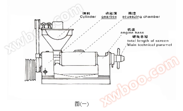
2、 Installation of the machine:
The oil press must be installed on a solid foundation with anchor bolts to keep the machine level. The motor is installed on the back of the feeding hopper.
3、 Lubrication of the machine:
1. Oil presses mainly use two forms of lubrication: oil and butter. The refueling cycle is shown in Table 2
|
serial number NO |
Lubrication parts lubrication |
Types of oils and fats lubricate |
Refueling cycle Time span |
Oil change interval Lubricate replacement period |
1 |
Adjusting bolt Adjusting bolt |
20Mechanical oil Mechanical oil NO.20 |
per class2time 1-2time/day |
|
2 |
bevel gear Bevel gear |
20Mechanical oil Mechanical oil NO.20 |
per class2time 1-2time/day |
|
3 |
bearing sleeve Bearing bush |
20Mechanical oil Mechanical oil NO.20 |
per class2time 1-2time/day |
|
4 |
gearbox Gearbox |
20Mechanical oil Mechanical oil NO.20 |
First refueling12kg |
six months |
5 |
Each rolling bearing bearing |
lubricating oil Grease |
once a year |
4 Machine operation:
(1) Key points before starting up:
Before starting up, fill the gearbox with 12 kilograms of engine oil
After installing the machine, add lubricating oil according to regulations, check whether all components are fastened, and whether the operating handle and plug plate are flexible
3. Use your hands to move the large pulley and check for any looseness or jamming of the machine. If there are any abnormalities, promptly eliminate them
4. Adjust the tightness of the belt, start the motor, and check if the direction of the pulley is consistent with the marked direction
After the preparation work for the inspection is completed, loosen the locking nut and screw the press screw to the dead center, then retract 3-4 turns, and move forward half a turn to ensure the gap between the press screw and the cake outlet
(2) Power on:
1. Start the motor, start the machine, add 6% -8% moisture to the cake, pour it into the hopper, polish the pressing chamber, and do not feed too vigorously, otherwise it may cause the pressing chamber to be blocked and the machine to jam. Therefore, the feeding should be started slowly and evenly. After the pressing chamber is polished and the cake is discharged normally, the embryo can be poured into the hopper
2. After operation, observe the condition of the cake. If no cake is produced, retract the press screw 1-2 more times. If no cake is produced, stop the machine for inspection Remember to avoid driving with a car After troubleshooting, proceed with the initial pressing operation During normal operation, the cake is 1-2 millimeters thick, shaped into tile like sheets, non stick when pinched by hand, smooth on the inside, wrinkled on the outside, and free of oil stains on the surface
Adjustment of cake thickness: Move the handle on the adjustment screw and rotate the adjustment bolt clockwise. If the bolt is turned outward, the cake will be thicker, otherwise it will be thinner. (Adjust the bolt to the left T165x6) The cone angle of the cake removal ring and the slag removal tip is different, and the thickness of the cake changes by 0.4-0.5 millimeters per revolution.
During the operation of the oil press, the oil and slag discharge should be checked regularly. Normally, most of the oil flows out from the strip and the first few sections of the garden. If the cake breaks into a residue, it indicates that the raw material is too dry. If the cake is found to be hot (emitting steam) in large patches, it indicates that the moisture content is too high, and the moisture content of the embryo should be adjusted in a timely manner.
Slag discharge: When the slag is discharged in fine flakes, it indicates high moisture content. If it is in powder form and contains foam, it indicates low moisture content. Excessive slag discharge in the garden is due to the failure of the compression nut to tighten the circular discharge. The compression nut should be tightened. If the moisture content is appropriate, the strip discharge may not produce slag or produce less slag. A small amount of slag discharge from the circular discharge is also allowed. The moisture content of the embryo directly affects the oil yield, so the moisture content of the embryo should be controlled during pressing.
(3) Shutdown:
1. During normal shutdown, all the raw materials should be squeezed and bent, and the squeezing screw should be repeatedly pushed back several times to remove the material from the squeezing chamber. The cake should be placed at the end, and then the vehicle should be stopped
2. If there is a power outage or sudden stop due to other accidents, cut off the power first, remove the discharge baffle, manually reverse the large pulley, and exit the billet when the spindle is reversed. Immediately push the screw shaft out of the squeezing chamber (when it is difficult to reverse the large pulley manually, do not force it to avoid damaging the machine), and clean it If it cannot be pulled out, the pressing nut should be loosened, the upper pressing cage should be removed, and the circular rows should be loosened one by one with a screwdriver, cleaned, and not driven again without cleaning
Five Disassembly and assembly of main components of the machine:
1. Disassembly and assembly methods for main components:
(1) Disassembly and assembly methods for squeezing cages (including round ribs and pork rib rings):
Rotate the screw shaft to extract the screw from the squeezing chamber, then insert a 24mm thick iron rod into the hole of the pressing nut at the end of the cake. Rotate the nut counterclockwise to loosen it: loosen the four M16 connecting screws at both ends of the upper squeezing cage, remove the 12 M16 bolts connecting the upper and lower squeezing cages, and remove the upper squeezing cage to remove the circular ring.
(2) Disassembly and assembly method of the strip:
Remove the pork rib ring and place one end of an iron rod against one row from the side. Tap the other end with your hand to knock out one row, and the remaining rows will automatically loosen
(3) Assembly method of strip:
Stand up the strip ring, with the oil outlet facing downwards (it is recommended to place a wooden board underneath), and arrange the strips neatly on the inner wall one by one. The end with a deep oil groove faces downwards, and the two rows of deep oil grooves cannot be placed facing each other. If the last strip is loose, iron sheets can be added between the strips to make them tightly adhere to the inner wall until there are no protrusions when touched by hand.
(4) The installation method of the squeezing cage:
Place the oil outlet groove surface of the strip ring facing the frame, and then insert it into the circular row in sequence according to the circular row number. Bring the oil groove face towards the frame. Then use the compression nut to hold the round row with fewer buckles, and install the squeezing cage. Both the upper and lower squeezing cages are manufactured in pairs, and if they need to be replaced, they need to be replaced both up and down. Use the removed bolts to tighten them alternately one by one.
Online inquiry
-
Contacts
-
Company
-
Telephone
-
Email
-
WeChat
-
Verification Code
-
Message Content
-